Hi, I’m Bryn, also known as canmom! I just joined Holonautic as a programmer and artist.
You can see a little of my personal WIP project THRUST//DOLL here. It’s a high-speed 3D bullet hell game where you’re a jet-powered cyborg, created in pure DOTS—that is, Unity’s new high-performance Entity Component System framework. While I made THRUST//DOLL, I wrote a lot of extremely detailed devlogs, a tradition I’m eager to continue here. I’m also a huge animation fan, and once upon a time I was a physicist.
This is the first in a series of posts about what I’m making at Holonautic. I’d like it to be an accessible introduction to some pretty technical subjects. Today the subject is water.
Contents
Contents
Water
My first task at Holonautic was to make a water shader.
I can’t talk too much about the game this is for, but it involves tiny figures on procedurally generated terrain. When I joined Holonautic at the beginning of May, Roger had already created a very impressive system for generating terrain over multiple frames using marching cubes and voxel noise. But it was missing the lakes/sea to surround this terrain.
Water in videogames is in some senses a ‘solved problem’. Modern games such as Valheim have gotten very good indeed at creating beautiful-looking water in real time, whether calm or stormy. You can find excellent tutorials for rendering stylised water. For example, Alexander Ameye has a fantastic page on creating a water fragment shader with noise-driven ripples, depth based fading, refractions, reflections, foam, and all the other effects you might want. Catlike Coding has a fantastic article on displacing water surface using Gerstner waves—more on that in a bit.
And if you want more realism still, you can use techniques like advancing the water in Fourier space, as demonstrated by Jump Trajectory in this video…
However, the big problem is that most of this would tank performance on the Quest 2. And thus began my quest to understand water so I could create some water that’s pretty but also performant…
Rendering for VR
When you’re rendering for VR, performance isn’t just a high priority, it’s absolutely mandatory. If you drop below 72 FPS, the rendered VR position will lag behind the player’s actual real-world position, so you are likely to induce motion sickness in the player. You cannot do that, it’s rude and also dangerous. VR games can’t chug framerates now and then—they must always be perfectly smooth.
There’s broadly two types of VR game in the world today. ‘PCVR’ is VR that runs on a gaming PC, and can basically take advantage of all the rendering techniques that regular computer games can use. Since you essentially have to render everything in the scene twice, once for each eye, this imposes certain performance constraints and makes certain operations a bit more fiddly, but ultimately PCVR games can do pretty much anything a regular ‘flat screen’ game can do. The same is true for VR that runs on consoles like the PS5.
However, Holonautic’s games target the Oculus/Meta Quest 2. This is a standalone device running Android. Since it’s affordable and doesn’t require a beefy gaming PC, it’s become one of the most popular headsets. But by the same token, the Quest 2’s graphics are drawn by a phone GPU—one that was high-end when it came out in 2020, but it’s got some major limitations compared to the sort of GPU power you find in a PC or console. A lot of standard techniques are total non-starters.
There are further wrinkles still. Those wrinkles have to do with how you get your data onto the GPU. I’ll discuss that in the next article.
In this one, I’m going to be talking a lot about vertex and fragment shaders. If you’re not familiar with these concepts, here’s a brief overview…
A quick introduction to shaders
A GPU (Graphics Processing Unit) is a machine that’s designed for a very specialist task: running loads of floating point calculations in parallel. Nowadays, nearly every computer has one, either a standalone component or a special part of the main CPU. In addition, the GPU has its own store of memory (known as VRAM) and takes care of sending pixels to the screen.
In the old days, GPUs worked on a ‘fixed function’ pipeline. The GPU gave you specific limited ways to do common operations such as projecting triangles in perspective, and a handful of ways of calculating lighting. Starting in the early 2000s, GPUs started to appear which let you run your own custom programs at certain stages in the pipeline, which are known as ‘shaders’. This proved to be so powerful that nowadays essentially everything is done with shaders.
Shaders are essentially pure functions. They run in parallel for every element in the source data, so they cannot have side effects or talk to each other. You write them in specialist languages like GLSL and HLSL, compile them and upload them to the GPU.
GPUs still primarily work using a method known as rasterisation. If you would like to learn about this in detail, I highly recommend Scratchapixel, which is a fantastic free course in computer graphics. Compared to raytracing, the major paradigm in pre-rendered graphics, rasterisation is much, much, faster, but it’s also more limited.
Here’s a summary of what happens when you draw an object with a GPU—in graphics language, a draw call:
- You feed the GPU a list of vertices—points in 3D space—and triangles, which are essentially just a list of three vertices. You say to the GPU, I want to draw these triangles with these shaders and these material settings. This is the render state.
- These vertices are defined relative to the centre of an object. We call this coordinate system object space or local space.
- As well as a position in 3D space, a vertex can have other data attached to it. For example, it might have UV coordinates. It also has a normal, which is a direction that points directly ‘outwards’ from the surface at this point.
- The GPU runs the vertex shader on every single vertex. The vertex shader’s main job is to take the points in object space and project them to a position on the screen and distance from the camera plane, which means they get a position in a new coordinate system known as screen space.
- To do this, it needs to take into account where the object is located in the world, how it’s rotated, etc., and the same for the camera, and also correctly put it in perspective. This is done by multiplying every single point’s position using a matrix called the Model-View-Perspective matrix, or Local to Screen matrix.
- The vertex shader is a fully programmable shader, so you can do other stuff here too! The most common thing you might want to do is displacement, which is moving the vertices around. Or perhaps you can create a ‘billboard’ effect by always rotating the object to face the camera.
- The GPU takes the transformed vertices and runs the ‘rasterisation’ algorithm. This takes each triangle and converts it to fragments. In the simplest case you create one fragment for every pixel on the screen that falls inside a given triangle, but you might draw extra fragments, e.g. for certain types of anti-aliasing.
- For each of these fragments, it then interpolates the values defined on the vertices, taking into account perspective, so they smoothly move between the points on each vertex. So each pixel gets, for example, its own normal and UV coordinates, which is a perspective-weighted average of the values on each of the three vertices of the triangle.
- Next, the GPU runs the fragment shader. The fragment shader’s job is to take the data associated with each fragment, and figure out what colour it should be, taking into account lighting, textures, etc. This is where things tend to get complicated! But ultimately, the fragment shader does some calculations and returns a colour. (It can do more than this, but let’s keep it simple for now!)
You have to do all the above for every object in your scene. Each object writes its colours to the colour buffer and its distance from the camera to the depth buffer. (A buffer is a place where data is stored on the GPU.) The depth buffer (aka z-buffer) is used to calculate overlaps and intersections. You can also use it for post-processing effects like fog. If a fragment is nearer to the camera than the current value in the depth buffer, we will use the colour it calculated. If the fragment is further away, we’ll keep the current colour. For transparent materials, we blend the new fragment with the colour buffer using the alpha value.
Once everything is drawn, we can apply post-processing effects (which are special fragment shaders that run on the whole screen), then copy the colour buffer onto the screen.
There are other types of shader that can exist. For example, compute shaders are basically ‘do anything’ shaders. You say ‘here is some data, do this to it and store it here’. Compute shaders are used for things that take advantage of the power of the GPU to do huge parallel iterations. One of the big uses for them is simulating particles.
There are various methods for saying ‘I can’t see that, no need to draw it’, which is referred to as culling. For example, you might skip drawing the back sides of triangles (backface culling), or objects that are outside of the area the camera can see (frustum culling). Some of this culling can be performed on the CPU, some of it is done on the GPU itself. In this way, we try to only run the fragment shader for pixels that are actually visible, to avoid wasting time on the GPU.
OK, hopefully that sufficies for a brief summary! We’ll see examples of how these different types of shader are used in what follows.
The shader graph
Writing shaders is fiddly. You are generally using a low-level C-like language (GLSL or HLSL), and there is often a lot of boilerplate involved. Reasoning about the flow of your program can be tricky.
Unity has a very useful tool to make this process simpler, which is the Shader Graph. If you’ve used material nodes in Blender, it’s pretty similar. Each node in the shader graph is a function, and you represent the flow of data by lines between boxes. At each stage, you get a handy preview.
More on how the shader graph works
The available nodes cover a lot of common operations you might want to do, from simple mathematical operations like multiplication to more involved functions like generating noise. But if you find it’s missing something, you can write a snippet of HLSL and include it as a ‘custom function’ node.
In its current form, vertex and fragment shader live in the same file. Part of the shader graph represents a vertex shader, and part of it represents a fragment shader. They can’t directly talk to each other - a node can’t connect to both the fragment shader and the vertex shader.
Data generally flows from left to right. You create input nodes that represent information available in the shader, such as the position and normal, or UV coordinates. You process them, and then eventually connect them to a node on the right which represents the output of the shader. (Depending on the shader type, there’s some additional processing done on this output.)
Whenever you save your shader graph, Unity generates the corresponding source code for a shader in HLSL, usually thousands of lines long. This shader is compiled and optimised just as if you’d written it in HLSL from the start. But the shader graph also lets you preview smaller pieces of your shader, showing you the effect of each transformation of the data along the way. This is great, since it lets you build up complex effects step by step, with constant visual feedback.
So, knowing what our tools are, our goal is to create a water effect. The water should be animated, and it should reflect light in a pleasing way as you move your head around the scene in VR.
What does water look like?
A stereotypical, symbolic representation of water is that water is blue, and you might draw a web of little white lines on top, representing something like caustics, or maybe foam, or reflections—don’t think about it too hard. This is a familiar cartoon representation of water. It doesn’t really look like water—if an opaque blue fluid with white lines on it came out of your tap, you would be pretty worried!—but it communicates the idea of water.
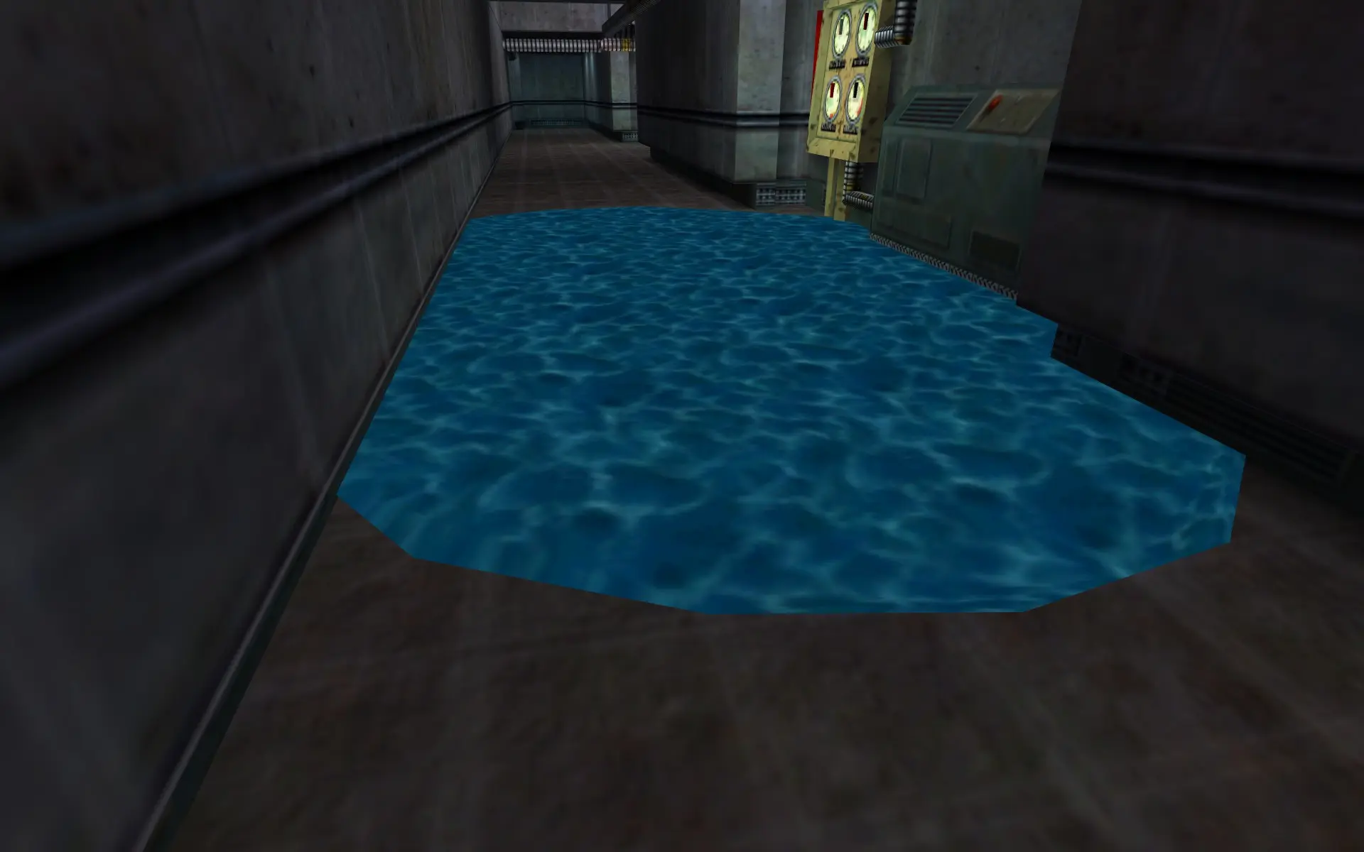
Water in Half-Life (1999).
This is the approach used in early 3D games such as Half-Life. In 1999, the programmers at Valve didn’t have highly optimised GPUs with thousands of programmable shader cores. Blocky, opaque water was the way to go. It was also possible to make the water transparent with alpha blending, which you see in a few levels in Half-Life.
We could imagine taking it further, painting the opaque water more carefully. But ultimately it would look ‘wrong’ because it doesn’t reflect light in the way we’d expect when we move around it.
Diffuse and specular reflection
To get better looking water, we need to understand how light behaves at its surface. To brush over a very long and complicated story, when light approaches flat interface between two materials with different properties, the energy has to go somewhere. Three things can happen. It can reflect, travelling away from the interface. It refract, meaning that it can pass through into the other material, changing its direction according to Snell’s law. Or it can be absorbed, meaning that light doesn’t go anywhere. (The energy will promote an electron to a higher-energy state; it might then be re-radiated in a different part of the spectrum.)
Computer graphics is most concerned with the first category, reflection. There are, broadly speaking, two types of reflection that we model. Specular (mirror-like) reflection sees the light bounce off at a single, specific angle. The rule is essentially you flip the direction of the light ray along the surface normal.
What is a normal?
A normal is a vector that points directly ‘outwards’ from the surface.

The blue arrows are the normals at various points on the surface. [Source: Wikimedia Commons, CC0]
#/media/File:Normal_vectors_on_a_curved_surface.svg)
In 3D graphics, we use them in basically all shading calculations. You can easily compute the normals at every point on a flat triangle using a vector cross product. But in graphics, we often want to approximate smoothly varying surfaces. The way we do this is make it so that, instead of each face having a normal, each vertex has a normal. Like other vertex data, we can then smoothly blend (interpolate) the normals across the triangles.
We can do more than this. For example the fragment shader can adjust the normals before calculating shading, perhaps by using a texture called a ‘normal map’. This is a great way to simulate small bumps and details on a surface without having to make extra triangles. Unless you view the surface at a steep glancing angle, it will be hard to see the difference between a normal map and real bumps.
Meanwhile, diffuse reflection sees light bounce off the surface in a completely random direction, spreading its energy evenly. For geometric reasons, there is a cosine factor involved—light that shines directly on a surface will make it look brighter than light that shines at a glancing angle, which spreads it out. Diffuse reflection is an approximation of the complicated interactions that take place of a surface that allows the light to enter and bounce around a bit before leaving.
In a path-tracer, these interactions are relatively simple. You trace a ray from the camera until it hits a surface. You reflect it off the surface in a random direction, and attenuate it by a function called the BSDF to take into account the ways it can reflect light. Then you keep following the ray. Eventually you direct the ray to a surface that emits light, such as the sky, and stop. This tells you the contribution of the ray. You shoot out many thousands of rays, exploring all the different ways that light can bounce around the scene.
This is a very flexible framework, with room for just about any possible way that light can interact with surfaces: reflection, refraction, subsurface scattering. It naturally gives you indirect light, and with certain tricks, you can even get caustics. But it’s relatively slow. Every step along the way, you have to test a ray against the whole scene to see what it hits. There are many clever tricks to speed it up, but it’s only recently become possible in real time, on the highest-end graphics cards which have specialist hardware for raytracing.
In rasterisation, you can’t do anything like that! You have fragments which only know a very limited amount of information about the world. So you have to use tricks.
Metals and dielectrics
Modern day graphics works in a paradigm called Physics Based Rendering. You can read a great deal more about it in books like Physics Based Rendering: From Theory to Implementation. Just about every modern game uses techniques derived from PBR. Unity’s HDRP and URP Lit shaders are both implementations of a PBR ‘principled’ shader, which goes back to research at Disney.
Materials in physics-based rendering are usually categorised into two types. These are metals and dielectrics. Metals, due to the way their conduction-band electrons interact with light, exhibit entirely specular reflection. The specular reflection may be coloured, meaning some frequencies of light are not reflected—think gold or copper.
Dielectrics is the ‘almost everything else’ bucket. They’re more complicated. At glancing angles, they show specular reflection according to the Fresnel effect. These equations say that, depending on what angle light approaches the surface of a region with a different refractive index, some of it is reflected and some of it is transmitted inside the surface (refracted). At the most extreme glancing angles, all the light is reflected specularly. But at head-on angles, light passes into the material. For some materials like glass with very low absorption, it is likely to carry on all the way through the material and out the other side. For other materials like plastic, wood or ceramics, light doesn’t get very far before bouncing off of internal structures and pinging around, before exiting at a pretty much random angle. So seen dead on, diffuse reflection dominates.
The specular reflection from a dielectric material is not coloured. Shine a white light on a dielectric material at a glancing angle, and get a white highlight.
On top of these two reflection types, there is a factor called ‘roughness’. This takes into account that the surface of a material might be covered in tiny little bumps that break up the specular reflection and spread it out. A smooth surface illuminated by a bright light will have bright, point-like specular highlights; on a rougher surface the highlight will spread out and become indistinct.
(Standard PBR principled shaders are enough to cover most materials in the world pretty well, but they’re not universal. For example, the tiny structures on a CD-ROM or the wings of a moth create complex diffraction effects. And for more stylised rendering, you may often want to exaggerate effects or break physics.)
Realtime rendering: the world of hacks
So, if you wanted to render water in a strict, physically accurate way using a path-tracing renderer like Cycles, you would set it up to have a transparent surface with the correct refractive index, and a volume which adds a component of scattering to rays traced through the bulk of the material. Physics would do the rest. (You’d still have to figure out a good way to simulate the waves and ripples on the surface of the water, mind you!)
In realtime, we can’t do that. We have to fake it.
On any given object, lots of different light is coming in and reflecting from it at once. There’s light directly arriving from light sources such as the sun, and there’s light that’s reflected or refracted from other surfaces. This might seem impossibly complex, but there are some saving graces. There are almost no surfaces that are perfectly reflective—usually some amount of the light is absorbed. Moreover, thanks to diffuse reflection and roughness, the energy of the light gets spread thinner and thinner. So you only really have to worry about the first few bounces from a direct light.
The contributions of all the other light bouncing around from all sorts of different surfaces—the sky, the ground etc.— is treated as an average, constant value that shines evenly on everything in the scene. This is called the ‘ambient light’.
Simpler speculars
This means we only need to consider a couple of cases to get pretty close to what we really see. The first case is the light that comes directly from a light source. In Unity, and many other game engines, there is usually one light that is much brighter and more important than all the other lights, the ‘main light’. This might be, for example, the sun.
This scheme simplifies the calculation immensely. You don’t need to know about everything in the scene, just the main light, which creates a bright spot known as a specular highlight. By comparing the view direction with the main light direction and the surface normal, you can figure out how much specular reflection comes from the main light. You simply ignore all the other specular reflections. This is nice and simple.
This approach works well enough if the surface is a little rough, so you wouldn’t really expect to see a mirror-like reflection. For rough materials, this is often plenty, because the specular reflection is usually too weak and spread out to see anything more than the bright highlight that comes from reflecting the main light. You render the diffuse and specular from the main light, add in some constant ambient light, and you’re done.
However, for a smoother surface, like a highly polished floor, a mirror or the surface of a lake, this isn’t really enough. Other things need to be reflected too or it will look very unnatural. So we also need to consider light that comes from a light source, then bounces off some random object in the scene, then bounces off our object, at just the right angle to hit the camera.
Hold this thought, we’ll come back to it in a bit.
A recipe for water
You might say, well, metals are conductors, and they are purely specular. Well, water conducts electricity too, so shouldn’t we treat water as a metal? Surprisingly, no, you shouldn’t. Water is best modelled as a dielectric: like glass, at glancing angles it has strong specular reflections but viewed dead-on it transmits almost all the light. I’m a little vague on why this is, but if I had to guess, it’s that it’s not the water itself but ions dissolved in the water that conduct electricity. These ions are a relatively small part of the bulk, and much less mobile than the electrons in a metal, so perhaps they’re not really relevant for light-water interactions. If someone knows more about this, I’d love to know!
However, among dielectrics, water is not like a material such as plastic which is pretty much opaque. Light can penetrate a long way into water. But water isn’t perfectly clear either: over longer distances, it gradually absorbs energy from the light, which is why the bottom of the ocean is very dark. This absorption is frequency-dependent: shorter wavelengths like red are absorbed more than longer wavelengths like blue. So there is a sense that water is blue. You just need a lot of water for its blueness to become evident.
For this reason, the way we render water then has a lot to do with how much water there is. A glass of water is pretty much clear—almost no light is absorbed passing through it. But if we are looking down on the ocean from above, very little light is going to make its way up to us after reflecting from the bottom of the ocean. So we only really see the light that reflects from the surface, or scatters somewhere in the few metres below the surface. (The ocean is also generally full of floating sediment, which makes the water foggier).
If you’re rendering a more intermediate scale, such as a river flowing in a forest, you probably can see the bottom of the river, but of course the light that bounces off the bottom of a river is going to be distorted by refraction. Additionally, the light that comes down to the surface from the top of the water is also going to be refracted, creating a pattern of bright lines known as caustics.
![Photo of caustics on the bottom of a pool lit by bright light from above. [Source: <a href='https://commons.wikimedia.org/wiki/File:Great_Barracuda,_corals,_sea_urchin_and_Caustic_(optics)_in_Kona,_Hawaii_2009.jpg'>Brocken Inaglory on Wikimedia Commons</a>, CC-BY-SA]](https://canmom.art/img/embed/gamedev/holonautic/caustics.webp)
Graphics is all about clever approximations, realtime graphics even more so. For example, rather than simulate every wavelength of light, we keep track of just the three colour primaries. Rather than simulate how water flows, we find an easy-to-compute noise function that creates an appearance like water ripples.
So, based on the situation, we may want to put different effects in our shader. If you’re rendering clear water, refraction is most important, and you don’t need to reflect the whole scene. But if you’re rendering a large body of water, seeing what’s under the water is less important, and reflections are much more.
Realism is not our god
We also have the artistic freedom to stylise and break from realism. Realism is something that must be applied judiciously. The game we’re making is a stylised one, overly realistic water would seem out of place. Art is about abstraction, simplification, distillation. When you paint a picture of water, you’re showing me what you see when you look at water, the interesting ways you can play with the image of water. I want to give you a powerful impression of water, water arranged by human hands.
So let’s have a look at how a few humans have depicted the sea…
Ivan Aivazovsky
Let’s begin with Ivan Aivazovsky, one of the most renowned painters of the sea. Here, for example, is The Ninth Wave.
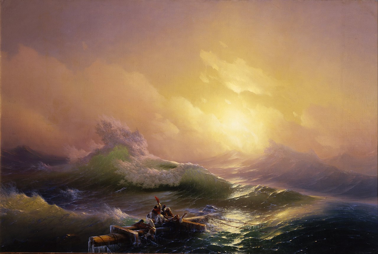
I got to see one of Aivanovsky’s paintings in St. Petersburg almost a decade ago, and I still remember how much it awed me when I turned the corner to face this incredible wall-sized vision of the furious ocean. Aivanovsky’s paintings show an amazingly sharp appreciation of how light interacts with water, but he does not paint “photorealistically”. Instead, he exaggerates and pushes the effects he wants to emphasise. The lighting is more stark, the glow of light scattering through the waves stronger. The scene is carefully composed to lead our eye around and create the most drama.
Still, let’s have a look at what Aivazovsky wants us to see in water. We can see the reflection effects talked about so far. The scene is harshly lit from a powerful light source in the distant fog. This backlight means we can see both specular reflections (which form a line towards the light source, the ripples spreading the reflection vertically) and transmission (subsurface scattering), with the relatively thin waves lighting up with a brilliant green glow from inside where the light passes through them.
Elsewhere, where our gaze hits the water more directly, the water is dark. There is no water coming up from the deep ocean. There is, furthermore, atmospheric perspective: the waves further away from us blend into the clouds, getting pinker and less saturated.
We can also look at the shape of the waves. There are both large waves, which are breaking in splendid spray, and small choppy ripples on the surface. The waves form sharp cusps, which is where spray tends to form, or even roll over and break.
Shigeko Inoue
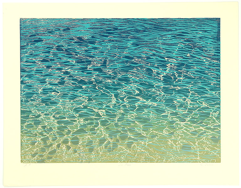
While I was working on this shader, I came across the woodblock prints of Shigeko Inoue. Here are a couple of her depictions of the sea…
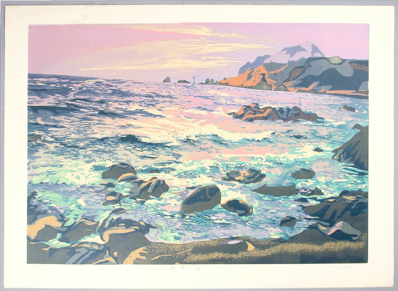
The Sea of Sado, Shigeko Inoue
In contrast to Aivanovsky, woodblock printing means that Inoue uses much harder-edged shapes—but by the same token, she can make them incredibly intricate. The first picture shows water that largely reflects the sky, with its pink sunset colours, interrupted by patterns created by small ripples changing the normal direction and thus the direction of reflection. In the foreground, we start to get some more blue colours as the waves break around the rocks.
The second picture depicts a shallower sea. It shows a web of bright caustic-like highlights, crossing over the broader blue shapes which creates a startling illusion of depth. The yellow colour fading in at the bottom suggests the bottom of the sea, with the increased transmission of the Fresnel efect; further away, we have these long sharp curving shapes showing where ripples break up the reflection of the blue sky.
Children of the Sea (Studio 4°C)
It’s not just painters. Water is a subject that has long been of fascination to animators. (I love animation, and I write about it obsessively. One thing I’m really eager to do is to cross the streams of sakuga fandom and 3D rendering.)
Compared to paintings or woodblock prints, traditional animation has to simplify the light and shadows a lot more to create something that’s practical to draw in motion. Which doesn’t mean it isn’t often unbelievably complex.
Children of the Sea, by Studio 4°C, is a film of overwhelming spectacle. Its depiction of water and ocean life combines traditional animation and CGI in the way that Studio 4°C do better than anyone. Its sequences cover an incredible range, from calm sees reflecting towering clouds through a colourful coral reef with the camera passing above and below the water to a magnificent sequence of a whale breaching as the sun rises.
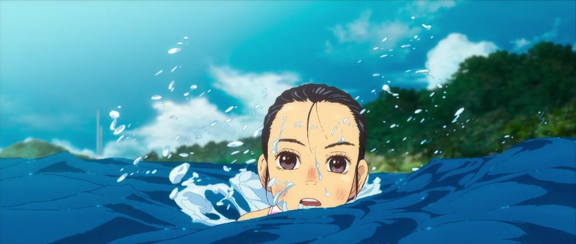
What’s especially notable is that in the hand-drawn scenes, Children of the Sea can achieve a spectacularly convincing and detailed depiction of the sea with only a couple of colours. Here, the dark and light shapes don’t represent shadows so much as areas where the specular reflection is broken up by waves and we see directly into the water. Or maybe they don’t represent anything beyond simply being shapes that suggest form. And while in many shots, Children of the Sea uses digital compositing tricks to make it hard to tell at a glance whether you’re looking at CG or a drawing, this shot shows how much animators like Kaori Hayashi and Sanae Shimada can do with just a few colours, lines, and shapes.
(It should also be acknowledged that all of this incredible technical complexity came at a terrible cost on its staff.)
Ride Your Wave/Lu Over The Wall (Science Saru)
The water in Masaaki Yuasa’s films like Ride Your Wave and Lu Over The Wall are more simplified and stylised relative to that of Children of the Sea, which isn’t to say they don’t have some incredibly complex shots.
Here we can see the different layers of effects. The darker and lighter shapes are used to indicate the pattern of ripples breaking up the sky reflection. The shape of foam is generally much noisier and more complex than the shape of the ripples. Towards the end of the scene, the lighting changes—this is a stylised effect that maybe doesn’t have a physical interpretation, but I believe it can be thought of as the light source moving behind the characters to silhouette them, so the specular reflection pattern inverts.
Meanwhile this cut by animation god Shinya Ohira shows that if you wield the dark and light shapes well enough, you can convey a feeling of water even if you make the water bright green or yellow.
There are many more examples of beautiful water in animation we could study, but that will do for now.
The first step: generating ripples
Before we can render anything, we need some geometry.
My first idea to render water was to do everything in the fragment shader. I would generate normals for ripples using noise samples, and then compute normals from this. So the water doesn’t need to be anything more than a flat plane, or quad: just two triangles.
Now, we gotta make it bumpy. I like doing things procedurally where possible, since it gives you a lot more control and ability to make it interact with other things in the game. What that means in practice is that you generate some noise. ‘Noise’ refers to the injection of randomness, mathematical functions that approximate some of the chaos found in nature.
Let’s make some noise, people!
There are a few standard ways to generate noise in computer graphics. These are described in detail in the book of shaders. These noise functions have to be really simple, so you can calculate them quickly for every single shader call. The shader graph defines three.
All of them need to be calculated in parallel, with consistent results. The way they do this is to use a lattice. They take as their input two coordinates known as UV coordinates, which in this case simply vary from 0 to 1 along each axis of the square. This space is divided into a grid, whose size you can tune. Each point is able to work out its nearest lattice points.
The other ingredient is a hash function, which rearranges numbers seemingly at random. Every time you call the hash function with the same input, you get the same output, but two nearby inputs aren’t correlated at all. So if you laid out the outputs of a hash function in order, it would look like random… well, noise. There are many different hash functions with different properties.
Simple noise
Simple noise is indeed pretty simple. It’s also known as value noise. The way it works is this: you evaluate your hash function for the four nearest lattice points. Then, you linearly interpolate those lattice points.
To create a more complex pattern, you can add up multiple noise evaluations at different scales. We call these different noise evaluations octaves, and the resulting pattern fractal noise. Unity’s noise function does this automatically, calculating three different octaves. So, despite its simplicity, the simple noise node actually ends up calculating twelve different evaluations of the hash function.
Gradient noise
Perlin noise is an extremely influential technique invented by (guess what) a man named Ken Perlin. Instead of finding a number at each lattice point, it creates a little vector. Then, it finds the dot product between this angle and the vector from that lattice point to the point where the shader is being evaluated.
The result of this is a bunch of tiny little blobs. If you look Perlin noise it looks weirdly like it’s out of focus.
Unity’s gradient noise, unlike the simple noise, only calculates one octave. Of course, you could add more if you fancied.
Voronoi
Now this one’s really special.
A Voronoi diagram works like this. You take a random bunch of points. Then you divide space up into regions around each point, which are defined as ‘everywhere closer to that point than all the other points’. This creates this interesting pattern that resembles cracks in a dry desert or broken glass.
The shader has two outputs. One is a random colour for each Voronoi ‘cell’. The other is a number, the distance to the closest point.
A truly generic Voronoi diagram would generate points completely at random. Then you’d test the distance against every single Voronoi point. This would be way too complicated, so we don’t do that. Instead, it’s lattices again. Each square of the lattice gets a point inside it. When we evaluate the shader, we work out which lattice square we’re in, plus the eight nearby squares, and figure out the closest Voronoi point. So the shader must evaluate nine different lattice sites, each one of which gets a 2D point. And each one gets a square root.
This is strictly speaking called Worley noise after Steven Worley, who figured out a practical way to use this idea in graphics in 1996. Catlike Coding has a fantastically detailed article on it here. In practice the underlying grid is usually not obvious for 2D Worley noise.
3D Worley noise does the same thing, starting with a 3D position, and generates a 3D lattice. That means 27 evaluations of the noise function. I’ve found it more noticeable in 3D Worley noise, but not too terrible. We’ll talk more about that in the next article.
The great thing about Voronoi noise is that it creates sharp edges that are hard to come by from the other noises, in a very organic pattern.
Distorting noise with noise
In practice, these noise patterns tend to stick out like a sore thumb if you don’t apply some creativity.
One of my favourite tricks is to distort noise using noise. This means, you calculate one noise sample using the actual UV coordinates. Then, you add this on to the UV coordinates, creating distorted UV coordinates, and you can use that to evaluate noise again.
The result tends to look much more interesting than the basic noise types. For example, here is simple noise distorted by simple noise.
Noise isn’t the only thing you can use to distort UV coordinates. Perhaps you might use something like the depth under the water to squash up the UVs near a shoreline to simulate ripples hitting the shore, or to draw a foam texture. By squishing the UV coordinates around, you can do far more than you could with just regular noise sampling.
The drawback of all of this is that each noise sample has a cost. If you have time for one noise sample in the fragment shader, you might not have time for three, or five. So you have to be judicious.
From noise to normals
To simulate the tiny bumps created by waves, we have to adjust the surface normals. We treat the texture generated by the noise as a height map, and then we invoke Unity’s Normal From Height node. This essentially calculates the numerical derivative of the height map function in the x and y directions, and uses that to work out the angle of the surface.
You might wonder (I certainly did!), how does the shader do that? After all, doesn’t the fragment shader only know about its own state, and not the state of any other fragment? Well, when I said that fragment shaders are pure functions of their inputs, that’s not quite true. In fact, the GPU calculates the fragment shader in square blocks of four fragments at a time, using Single Instruction Multiple Data (SIMD) instructions. This situation makes it possible to numerically estimate the screen space derivatives. Unity’s ‘Normal From Height’ node then transforms these screen space derivatives into world space or tangent space.
Once you’ve got the normals from the heightmap, you can add them to the original surface normal in order to do lighting with them. Let’s try it out.
Those big waves look all right, but real waves have a spectrum of larger waves and small ripples. We can make these interact with each other by adding the large waves’ noise sample to the UV coordinates of the ripples.
This doesn’t really look perfect, the Voronoi noise is a bit too sharp and makes it feel a little like plastic, but it does convey the gist of larger and smaller waves.
The devil of performance
I was pretty happy when I came up with this, but when I tried uploading it to the Quest 2 to test performance, it crushed the poor GPU into the dirt. The framerate fell well below the 72fps threshold: this fragment shader was just far too complicated. I needed another approach.
Waves in the vertex shader
About this time, I read Catlike Coding’s article on creating water waves. Since the expensive part of this shader seemed to be all the noise samples, I thought if I evaluated noise per vertex instead of per fragment, we might be able to win back some performance.
Morever, by displacing the water surface, the water actually moves up and down in a realistic way against the shore. Waves can occlude other waves. We can render much bigger waves.
The position of the waves can be calculated using something called a Gerstner wave. Real water surface waves are not a sinusoid, but a more specific shape with sharper peaks. (Physically, this is because the water has to physically flow in and out of the waves.) This can be approximated by having each point on the surface move in a small circle, horizontally as well as vertically.
Catlike’s article is an excellent overview of Gerstner waves, and helpfully includes computation of the normal as well as the position (necessary since we can’t use the fragment shader method to calculate normals!). To use displacement, we need enough geometry to show the detail, in essence a higher-resolution grid of vertices. So out goes the quad and in comes the “Big Plane”.
Just using Gerstner waves directly, however, produces waves that are much too even. To break them up a bit and add some more variation, we can add noise to the coordinates of the points before calculating the Gerstner wave, just like we did for the noise. This means the normal is strictly speaking incorrect, but it works well enough as long as the distortion isn’t too extreme.
I was delighted to find that the Quest 2 could handle this displacement just fine. On top of that, I added a much simpler noise evaluation to create some simple ripples. The displacement of the points causes the waves to interact nicely.
The lighting model
Simple Fresnel
Although the water is a flat plane, we want to convey the sense that there is a volume of water underneath. As we saw in Aivazovsky’s paintings, a large body of water reflects light strongly at glancing angles, but when we look at it dead-on, we instead see light that’s bounced around in the depths, which tends to be a dark blue-green colour.
For this reason, the primary component of water lighting is a Fresnel node. This calcuates the dot product between the surface normal and the view direction, and then subtracts it from 1, giving a number that varies between 0 (surface viewed dead on) and 1 (viewed almost parallel to the surface). Unity further gives us the option to raise this Fresnel factor to some exponent.
Unity’s Lit shader isn’t really appropriate here. The metallic shader has no Fresnel component, and the dielectric shader includes diffuse reflection that is incorrect for water. We could use a ‘clearcoat’, but it makes sense to keep things simple and use the unlit shader so we can do custom lighting.
We can then use this Fresnel node to interpolate between two different colours. When the Fresnel node is 0, we can show a darker blue-green colour. But what about when it’s 1? Strictly speaking, this is a specular reflection, so it should capture the whole scene. We’ll talk about doing that shortly. But for a lighting model that’s as simple as possible, we can just use a colour that represents the colour of the sky. This works best for open water with no land in sight.
Reflecting the main light
As well as the sky, it’s easy and not expensive to add a reflection of the main light (the sun). To get the most interesting reflections, it’s best to have the sun fairly low to the horizon. We can calculate the amount of reflection from the sun using a specular reflection model such as the Phong model. You can calculate this using (…)
Refraction
We can show things underneath the water by sampling the scene depth and colour buffers. As long as the water renders after everything else, we have a complete render of the scene, and the distance of every pixel from the camera. This is enough information to show underwater objects getting murkier with distance, and you can also distort the texture sampling coordinates using the same noise we used to generate the ripples. This is all discussed in Alexander Ameye’s article.
To do this, you need to enable some settings in the render pipeline and camera. The depth and colour buffers are generated regardless, but I think setting them up for texture sampling has some overhead.
Unfortunately, anything involving the scene depth and colour buffers seems to be really slow on the Quest 2. I’m not entirely sure why this is. It may be that by optimising the terrain we could win back enough performance to have this effect work. In any case, refraction was not that important, so I put it aside.
Better reflections
But I wanted water that reflects stuff! Specifically, I want the water to reflect the terrain.
There are various ways to handle reflections in real time graphics.
Environment maps
We could have a texture that contains a 360° full-sphere panoramic view of the world around a certain point. These might be a real scene photographed in a special way, generally known as an environment map or sometimes a ‘HDRI’. Or, they could be the actual 3D scene of the game, rendered from the point of view of a special point called a ‘reflection probe’. Then, the fragment shader can work out which direction of light would get specularly reflected towards the camera, and sample the corresponding point on the environment map.
If the environment represented by the environment map is much larger than the shiny thing we’re trying to render, this can work great. We can add tricks like blurring the environment map to represent a rougher reflection. Although the terrain geometry is generated at runtime, we can refresh the envmap from a script, so it’s not an ‘every frame’ thing.
The problem with using an environment map for water is that the envmap represents the scene around only one point. The further you get from that point, the greater distortion is introduced. This leads to completely nonsensical reflections…
Moreover, in Unity, each object can have at most two environment maps associated with it. Unity takes the location of the object, finds the nearest and second nearest ‘reflection probes’, and blends between them. This is a sensible approach if, for example, you have a character walking through a level, but it’s no good for water.
Box maps
A box map is a variant of an environment map designed for representing reflections from vertical surfaces around the edges of a box. Like an environment map, it’s a 360° all-direction render of the scene. However, when you generate and sample the environment map, you take into account the position of the reflection and wall. You can read about the details here.
Box maps are very powerful in certain circumstances. For example, I hear this mini golf game uses box maps to make water reflect nearby walls in its temple level.
The effect of a boxmap is as if a painting was standing at the edge of the box, displaying an orthographic projection of the whole scene beyond that point. Boxmaps only really apply when you’re trying to reflect a flat surface, or something pretty close to a flat surface. So for example if you want a shiny floor to reflect the inside of a room, or a puddle to reflect a nearby shopfront, box maps work well.
Unfortunately what we want is not really compatible with a box map.
Screen space reflections
Screen space reflections take advantage of sampling the scene depth and colour buffers. Starting from the point where you’re evaluating the reflection, you can get a direction, and then advance the ray forwards into the depth buffer until you hit something (a type of raymarching). This is done by transforming repeatedly between world space and screen space; you can read the details here.
Screen space reflection is an expensive effect even on a PC, and I’d already had problems with using the depth and colour buffers for refraction, so I didn’t try making it work in on the Quest 2.
Reflection camera
Having ruled out all of these other methods, what remains?
Luckily, we have one big advantage: the water is pretty close to a flat plane. We can therefore use a reflection camera. A reflection camera works by essentially rendering the scene twice. First, you render the scene upside down to generate the reflection, producing a render texture, which shows what would be reflected from the flat plane at each point. Then, you sample this render texture to find reflections. You can even take into account the normals to sample different parts of the texture (though you need to handle the case where this ends up sampling out of bounds, but you can just set the render texture to extend infinitely at the edges).
My first attempt to make this work was to use the script cited in Alexander Ameye’s article. This sets up a custom render pass that renders the reflection camera. Testing it on the flat screen, it worked well. However, in VR, the script got very confused. Worse, the performance wasn’t good enough, dropping to about 50fps.
At this point I discovered that someone had already done the hard work of solving this problem, and was offering a VR-compatible mirror on the Unity asset store. Better yet, I tested the provided demo and it had rock-solid 72fps performance even with multiple mirrors on screen. “What sorcery were they doing to make this happen?” I thought. So we bought the asset and I brought it into our game. While the reflections now worked correctly, the performance wasn’t really any better. Something was different between our project and the demo.
Fixing the terrain rendering
The problem is the terrain itself, I think. The terrain is generated in a grid of ‘chunks’, to spread out the work over a series of frames. Each square of the grid thus has its own model.
There is an overhead associated with every draw call. Each time you draw something, the CPU must tell the GPU what it has to draw. Just like talking to memory is much slower than doing things inside the CPU using the registers and cache, talking to the GPU is slow too. So you want to try to avoid changing render state as much as possible.
One of the tricks you can use to optimise the number of draw calls is ‘batching’. If you have a lot of meshes with the same material (same shaders and parameters), you can combine them into one big mesh and send it all to the GPU at once. However, combining the meshes can itself be slow, so there’s a tradeoff.
Our terrain is generated within Unity’s Entity Component System framework. Entities Graphics replaces a lot of the standard Unity pipeline, and it has its own facilities for batching draw calls. If two objects in the ECS have the same model, they will be batched. But objects with different models live in different chunks of memory, and each render in their own draw call, so for that reason, rendering the terrain is costing around 100 draw calls—a lot for the Quest 2!
Luckily, this situation is perfect for writing our own custom batcher. I can disable rendering on all the grid-square chunks, and copy all their mesh data into a single render mesh, cutting us down to just one single draw call for the lot.
Comments