originally posted at https://canmom.tumblr.com/post/159618...
Usually I write these posts while I’m working on the code, but this one had to be written after the fact as I lost internet yesterday.
Just do it in camera space, you silly girl!
So, I was still confused by how such things as the vector from surface to light, vector from surface to camera, and normal are transformed by the perspective projection matrix, renormalised by the z-divide, and transformed again from normalised device coordinates to raster space. I didn’t feel confident I’d be able to preserve the dot product between the normal and light direction through all that.
I had a look at some other graphics/OpenGL tutorials, but nobody seemed to be acknowledging the issue.
But in looking closely at an example of diffuse shader code in this tutorial, I realised they were actually bypassing this issue entirely, by keeping the vertex data from when it’s transformed only by the model-view matrix (i.e. in camera space), and using that to calculate the shading values. So, we can calculate the normals and light direction and dot product in camera space and needn’t worry about the perspective projection at all!
That will also help when we move on to Phong shading or another algorithm where the view direction is relevant.
That required some modification to a whole lot of different places, and to the main program section. The result is a huge commit.
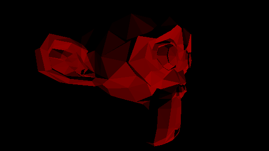
The result

Currently there is only one light, and the results are written exclusively to the red channel. Also the light isn’t exactly where I want it to be.
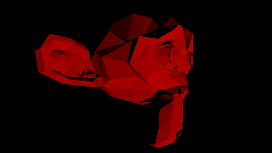
Still, I did my best to recreate this scene in Blender…

I’m delighted how close I got to the Blender result. There are differences, which I think are mostly to do with how the mesh is triangularised. Some surfaces seem to come out darker in my render than in Blender, which may be due to the light energy in Blender still being too high (I just fiddled with the slider until I got something similar). Still… nice???
The code
I split the function for the camera matrix in two:
mat4 modelview_matrix(const mat4& model,float angle) {
    //transform model matrix as for a camera pointed at the origin in the xz plane, rotated by angle radians

    mat4 modelview = glm::translate(model, vec3(0.f,0.f,-3.f));
    modelview = glm::rotate(modelview,angle,vec3(0.f,1.f,0.f));

    return modelview;
}

mat4 camera_matrix(const mat4& modelview,float aspect_ratio) {
    //premultiply a transformation matrix by a perspective projection matrix to make a camera matrix

    mat4 perspective = glm::perspective(glm::radians(45.0f),aspect_ratio,0.1f,6.f);

    return perspective * modelview;
}
This allowed me to make two vectors of vertex data, for camera and clip space (excerpted from main function):
//calculate model-view matrix
mat4 model(1.0f); //later include per-model model matrix

mat4 modelview = modelview_matrix(model,angle);

//add perspective projection to model-view matrix
mat4 camera = camera_matrix(modelview,aspect_ratio);

//transform vertices into camera space using model-view matrix for later use in shading
transform_vertices(modelview, model_vertices, camera_vertices_homo);
z_divide_all(camera_vertices_homo,camera_vertices);

transform_lights(modelview,lights);

//transform vertices into clip space using camera matrix
transform_vertices(camera, model_vertices, clip_vertices);
The call to z_divide_all on the camera_vertices_homo involves a lot of unnecessary divisions, since the w coordinate is 1 in each of the vectors transformed. An optimisation would be to write a function that simply drops the w coordinate, or a variant of the transform vector by matrix function that returns a 3-vector.
The lights also get transformed by the model-view matrix. This is done through new functions:
vec3 transform_direction(const mat4& transformation, const vec3& point) {
    //transform a 3D vector (implicitly in homogeneous coordinates with w=0) using a 4x4 matrix
    //and return a 3D vector, ASSUMING TRANSFORMATION DOES NOT MODIFY W

    vec4 homo_point(point.x,point.y,point.z,0.f);
    vec4 thp = transformation * homo_point;
    return vec3(thp.x,thp.y,thp.z);
}

void Light::transform(const mat4& transformation) {
    trans_dir = glm::normalize(transform_direction(transformation,direction));
}

void transform_lights(const mat4& transformation, vector<Light>& lights) {
    for (auto it = lights.begin(); it != lights.end(); ++it) {
        (*it).transform(transformation);
    }
}
This transformation function does in fact drop the w-coordinate. This seemed the easiest way to deal with it, but could lead to problems if it’s called with a projection matrix!
The triangle drawing function also had to be modified:
void draw_triangle(const uvec3& face, const vector<vec3>& raster_vertices, const vector<vec3>& camera_vertices, const vector<Light>& lights,
    CImg<unsigned char>* frame_buffer, CImg<float>* depth_buffer,
    unsigned int image_width, unsigned int image_height) {
    //draw all the pixels from a triangle to the frame and depth buffers
    //face should contain three indices into raster_vertices

    vec3 vert0_raster = raster_vertices[face.x];
    vec3 vert1_raster = raster_vertices[face.y];
    vec3 vert2_raster = raster_vertices[face.z];

    vec3 vert0_camera = camera_vertices[face.x];
    vec3 vert1_camera = camera_vertices[face.y];
    vec3 vert2_camera = camera_vertices[face.z];

    uvec2 top_left;
    uvec2 bottom_right;

    vec3 normal = glm::normalize(glm::cross(vert1_camera-vert0_camera,vert2_camera-vert0_camera));

    bounding_box(top_left,bottom_right,vert0_raster,vert1_raster,vert2_raster,image_width,image_height);

    //loop over all pixels inside bounding box of triangle
    //call update_pixel on each one to update frame and depth buffers
    for(unsigned int raster_y = top_left.y; raster_y <= bottom_right.y; raster_y++) {
        for(unsigned int raster_x = top_left.x; raster_x <= bottom_right.x; raster_x++) {
            update_pixel(raster_x,raster_y, vert0_raster,vert1_raster,vert2_raster, normal, lights, *frame_buffer,*depth_buffer);
        }
    }
}
What next?
I want to understand how to link C++ code with header files, and this file is getting extremely unwieldy and taking a noticeable amount of time to compile, so I’m going to split it up. I will also (since it shouldn’t be too difficult) add colour to the surface albedo.
I don’t want to spend a long time trying to implement different BDRFs when that would be better done in OpenGL proper. It might, however, be worth implementing texture coordinates, and smooth shading, to improve my understanding of barycentric coordinates.
Comments