originally posted at https://canmom.tumblr.com/post/159840...
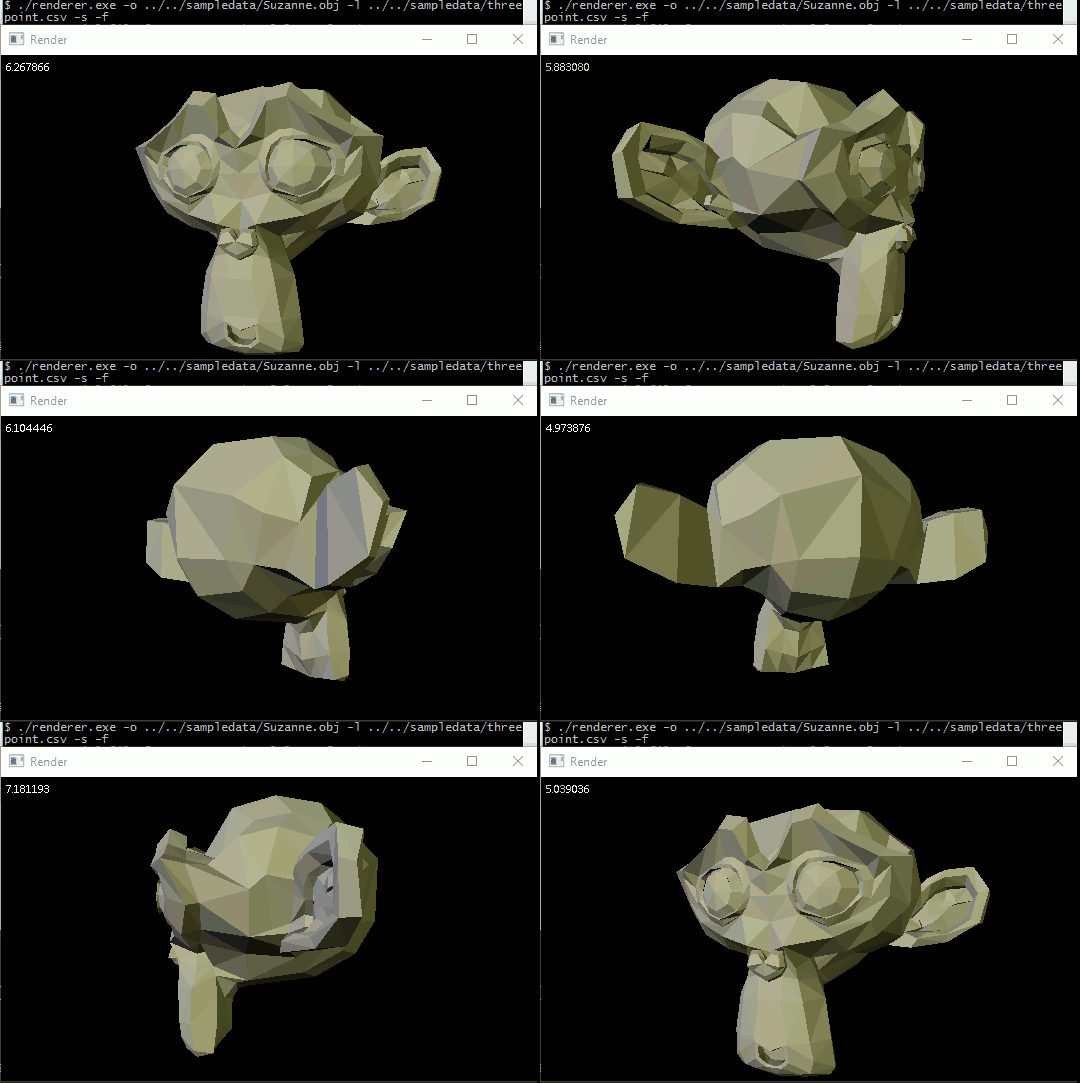
Animated output
I found a program to record my screen to gifs easily, so here’s what I couldn’t show you last time:
General perspective-correct interpolation
There’s one important part of the Scratchapixel tutorial that I haven’t covered, and that’s perspective-correct interpolation of quantities defined at the vertices over a triangle. (We’ve covered perspective-correct interpolation of depth, but not developed that to the general case).
Like before, I’m going to rederive the result derived on Scratchapixel, because if nothing else I find I learn things better when I work them out for myself.
So, say we have a scalar quantity \(c\) and depth \(z\), defined on vertices \(0\) and \(1\), which vary along a projected line with a parameter \(q\), and on the line in 3D space with parameter \(t\) so $$c=c_0 + t(c_1-c_0)$$ and $$z=z_0+t(z_1-z_0)$$Previously in part 7, we showed depth interpolates along the projected line as $$\frac{1}{z}=\frac{1-q}{z_0}+\frac{q}{z_1}$$
Scratchapixel procedes by writing $$\frac{c-c_0}{c_1-c_0}=\frac{z-z_0}{z_1-z_0}$$ then substituting for \(z\) and doing a ton of algebraic manipulation. I prefer not to just write huge blocks of algebra.
Instead, let’s notice that in the course of deriving the formula for interpolation of \(z\), we found that \(t=\frac{zq}{z_1}\). We can substitute this into the equation for \(c\), then the above equation for \(z\), to obtain \begin{align*}\frac{c}{z}&=\frac{c_0}{z} + \frac{q}{z_1}(c_1-c_0)\\ &=\frac{c_0}{z_0}(1-q)+\frac{c_0}{z_1}q + \frac{c_1}{z_1}q -\frac{c_0}{z_1}q\\ &= \frac{c_0}{z_0}(1-q)+\frac{c_1}{z_1}q\end{align*}
At some point I should properly work out the general case in barycentric coordinates, but I think we can reasonably predict from this what form it will take, i.e. $$\frac{c}{z}=\sum_i \frac{c_i}{z_i}\lambda_i(\mathbf{v})$$where \(\lambda_i\) are the barycentric coordinates.
But hold on a minute… we don’t exactly have such a function, rather, we have the output of our perspective matrix transforming to NDCs, which is to say, $$z_\text{ndc}=\frac{f+n}{f-n}+\frac{2fn}{f-n} \frac{1}{z}$$To be fair, since then we have made the world value of \(z\) also available, so we could use that, but divisions are relatively expensive and we’re going to have to do this for every pixel, potentially more than once depending on the order that triangles are rendered. What happens if we try to use \(z_\text{ndc}\) in place of \(\frac{1}{z}\)? Let’s say \(z_\text{ndc}=A+\frac{B}{z}\). We get $$\sum_i c_i \lambda_i z_{\text{ndc} i}=A \sum_i c_i \lambda_i + B \sum_i \frac{c_i}{z_i} \lambda_i= \frac{z}{c} + A \sum_i c_i \lambda_i$$
That last term is a problem. If we want to avoid divisions, we can calculate it as the screen-space linear interpolation of \(c\), and we’d have to pass \(A\) as well and subtract it. I was curious as to how OpenGL handles this issue, and the answer seems to be… perspective-correct interpolation is entirely handled by OpenGL itself between rasterisation (OpenGL-handled generation of fragments) and invocation of the fragment shader, so when you write a fragment shader, you need not worry about how to interpolate stuff. Sensible, and probably optimised to be much faster, but not ideal for learning.
I’m honestly not sure which of these methods would be faster. I could write it both ways and see how it goes I guess? But this isn’t exactly a fast renderer in any case, and I’m unlikely to need to worry about this once I’m writing real graphics code for OpenGL, so I’ll just figure out which one is most convenient.
Putting it in code
The first step is to write a general function for perspective-correct interpolation of colours, normals, texture coordinates, etc. etc. Then we can use that to create smooth shading, vertex colours, and indeed textures.
In fact we are already most of the way to such a function. In drawing.cpp, we have
template <typename T>
inline T interpolate(T v0, T v1, T v2, const vec3& bary) {
    //linearly interpolate or extrapolate a quantity v defined on three vertices in screen space
    //bary should contain barycentric coordinates with respect to the three vertices
    return bary.x * v0 + bary.y * v1 + bary.z * v2;
}
So we can write another function:
template <typename T>
inline T perspective_interpolate(T v0, T v1, T v2, float depth, const vec3& vert_depth, float offset, const vec3& bary) {
    //perspective-correct linearly interpolate or extrapolate a quantity v defined on three vertices in screen space
    //depth is the NDC depth of the target point
    //vert_depth should contain the NDC depths of the three vertices
    //offset should contain a correction equal to M_33 where M is the perspective projection matrix
    //bary should contain barycentric coordinates with respect to the three vertices
    return depth * (bary.x*vert_depth.x*v0 + bary.y*vert_depth.y*v1 + bary.z*vert_depth.z*v2 - offset * interpolate(v0,v1,v2,bary));
}
We also need to grab the value of offset and pass it down to this function when it is called.
What do we do with this?
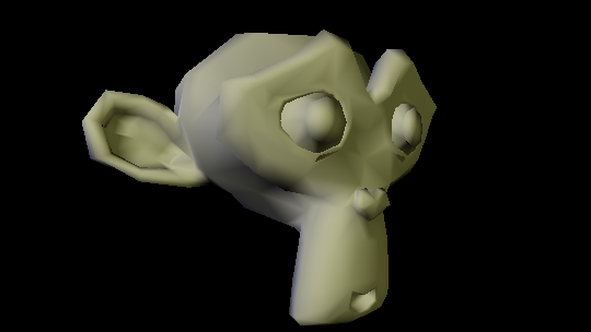
The most immediate thing to interpolate is vertex normals. By linearly interpolating vertex normals over a triangle at each pixel instead of using a single face normal, we allow light values to smoothly vary across the model instead of sharply changing at triangle boundaries. The effect is of course limited, because fundamentally the geometry is still big flat triangles, but it gives a pretty good approximation of a smooth surface without requiring us to use triangles smaller than a pixel.
This took several days to pull off, so I’m not going to summarise all the complications and mistakes and so forth. Essentially, what I needed to do is change my representation of a face - 3 vertex indices won’t cut it when vertex coordinates don’t necessarily correspond to vertex indices. So I had to rewrite everything to use a new header file defining a Triangle class…
#ifndef RASTERISER_FACE_H
#define RASTERISER_FACE_H

#include <array>

struct Triangle {
  //indices into vectors of coordinates, vertex normals, and uv texture coordinates for each vertex
  std::array<int,3> vertices;
  std::array<int,3> normals;
  std::array<int,3> uvs;
  Triangle(std::array<int,3> v, std::array<int,3> n, std::array<int,3> uv) : vertices(v), normals(n), uvs(uv) {};
};

#endif
Here I’m using the std::array container, which is a fixed-length container that’s rather less bare-bones than old-school C arrays (which were just pointers). I find it easier to think about passing an array object by reference than passing a pointer to the first value of an array.
I also needed to modify my file loading function to store the vertex normals it pulled out of a .obj file.
//convert the vertex normals into our format
for(size_t vert = 0; vert < attrib.normals.size(); vert+=3) {
    vertnormals.push_back(
        vec3(attrib.normals[vert],
            attrib.normals[vert+1],
            attrib.normals[vert+2]
        ));
}
And more significantly, store all the indices associated with a face, not just the vertex positions…
//convert the faces into our format
//faces should all be triangles due to triangulate=true
for(size_t shape = 0; shape < shapes.size(); shape++) {
    vector<tinyobj::index_t> indices = shapes[shape].mesh.indices;
    for(size_t face = 0; face < indices.size()-2; face+=3) {
        triangles.push_back(
            Triangle(
                {indices[face].vertex_index, indices[face+1].vertex_index, indices[face+2].vertex_index},
                {indices[face].normal_index, indices[face+1].normal_index, indices[face+2].normal_index},
                {indices[face].texcoord_index, indices[face+1].texcoord_index, indices[face+2].texcoord_index}
                ));
    }
}
I’m not sure what the name for a list in curly braces is, but it’s basically a literal for container types as far as I can tell.
So now we have vertex normals and indices into them. What next?
Smooths as sharks, aka sea puppies
So now we have vertex normals to interpolate, how do we do it? The key bit is this function in update_pixel…
//if smooth shading is enabled, update normal according to position in triangle
if(not flat) {
    normal = glm::normalize(perspective_interpolate(vertnormals[0],vertnormals[1],vertnormals[2],
        depth,vec3(raster_vertices[0].z,raster_vertices[1].z,raster_vertices[2].z),
        z_offset,bary));
    if (wind_clockwise) {normal = -normal;}
}
Of course that required a fair bit more code to get all the needed data down to the update_pixel function. If you want to, you can see all the details in the commit diff.
Anyway, I was literally jumping up and down when I finally got it working on Suzanne.
The feared & fabled Stanford Bunny
There’s a certain set of old ‘test models’ commonly used by graphics programmers when they want to try out a new program. The Stanford Teapot is probably the most famous, but it’s defined in a way that my program won’t understand. Another very common one is the Stanford Bunny. I thought it would be a good test of my program to see if I could render it, especially to see how quickly the program would render it.
I found a .ply version of the full Bunny (the original distribution was broken up into pieces), and an online converter that could turn it into the familiar Wavefront .obj. Unfortunately, there were some issues.
The immediate thing I noticed was that the model was tiny compared to the scales I’d been using before, like a tenth the side. Rather than hard code a scale factor, I decided to add another command line argument. The bunny was also above the origin, so I needed to move it down.
The other strange thing was that the model appeared to be rotated slightly compared to a lower-poly version of the Bunny. (Actually, something more interesting was going on…)
The first thing I did was change the model matrix to include a scale parameter. Only, that didn’t seem to be doing anything, except for some strange effects with clipping planes…
I realised that for some reason, the scaling matrix was being applied after the camera transformation. The culprit turned out to be the GLM transformation matrix functions, which are passed a matrix; I assumed they would left multiply the matrix by whatever new transformation you’re applying, allowing you to create a matrix for a succession of transformations. In fact, they right-multiply it - so if you call glm::rotate(somematrix,angle,vector) it creates a matrix where you apply the rotation, and then somematrix. This completely screwed up my intuition, and I decided to just pass the identity matrix to all these GLM functions, and handle the multiplications explicitly. It would hardly be a program bottleneck in comparison to the time-consuming drawing functions.
Initially, I only permitted rotations about the y axis, and was somewhat confused as to whether I was rotating the camera or the model. I decided I wanted full 3D rotations, and had to work out which of the numerous representations of 3D angles (Euler angles, [Tait-Bryan angles](https://en.wikipedia.org/wiki/Euler_angles#Tait.E2.80.93Bryan_angles), quaternions…) to use. Blender uses Tait-Bryan angles, but calls them Euler angles, which led to some puzzlement. I decided to go for YXZ Tait-Muller angles - this means rotating around the fixed z axis, then x axis, then y axis. I wanted the y axis last because I still wanted to spin objects round the y axis.
I ended up creating a relatively general function for a transformation matrix:
mat4 transformation_matrix(float factor, const vec3 & displacement, const vec3 & tait_bryan) {
    //create a matrix for scaling an object by factor relative to origin, rotating it by YXZ Tait-Bryan angles tait_bryan, and displacing it by displacement
    return glm::translate(mat4(1.f),displacement) * glm::rotate(mat4(1.f),tait_bryan.y,vec3(0.f,1.f,0.f)) * glm::rotate(mat4(1.f),tait_bryan.x,vec3(1.f,0.f,0.f)) * glm::rotate(mat4(1.f),tait_bryan.z,vec3(0.f,0.f,1.f)) * glm::scale(mat4(1.f),vec3(factor));
}
The transformations are applied in the order scale, then rotate, then translate. This function was sufficient to generate any model or view matrix I needed.
I decided to seperate the transformation of lights to the transformation of the model. Now lights are only transformed by the view matrix, not the model-view matrix, so when the model rotates, the lights stay fixed to the camera.
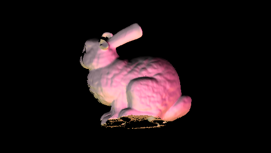
Something very weird was still happening. The lighting seemed off, and when animated, the rotating object seemed to make no physical sense at all (while the monkey was just fine). Eventually I realised that actually, I was viewing the inside of the model, that the normals on this model were somehow coming out opposite what I expected, so instead of backface culling, I was getting frontface culling…
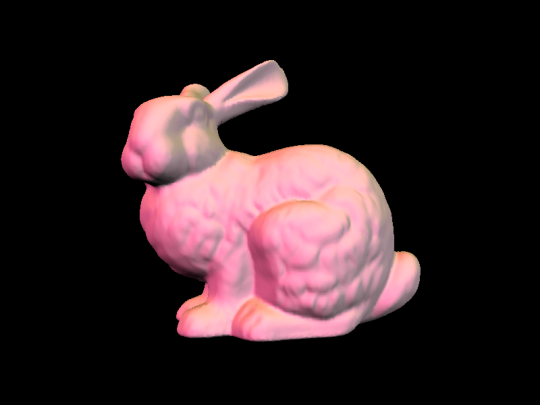
The culprit was the winding angle! Essentially, you can define triangles in one of two ways, with the vertices going anticlockwise round the normal, or clockwise. Because it fits my intuition about the cross product better, until now I’d been using anticlockwise winding angles, but this bunny was using clockwise ones! So I had to add some extra code to give a command line option to reverse the normals. Once I reversed the normals, backface culling and lighting worked correctly, and I finally saw a beautiful bunny.
So ultimately my arguments list grew like so:
TCLAP::SwitchArg flatArg("f","flat","Ignore vertex normals and use flat shading",cmd);
TCLAP::SwitchArg windingArg("","wind-clockwise","Assume clockwise rather than anticlockwise winding angle to determine backfaces",cmd);

//model transformations
TCLAP::ValueArg<float> rotxArg("","rx","Rotate by angle around x axis (composed as YXZ Tait-Bryan angles).",false,0.f,"radians",cmd);
TCLAP::ValueArg<float> rotyArg("","ry","Rotate by angle around y axis (composed as YXZ Tait-Bryan angles).",false,0.f,"radians",cmd);
TCLAP::ValueArg<float> rotzArg("","rz","Rotate by angle around z axis (composed as YXZ Tait-Bryan angles).",false,0.f,"radians",cmd);
TCLAP::ValueArg<float> scaleArg("m","scale","Scale the model by given factor",false,1.f,"factor",cmd);
TCLAP::ValueArg<float> dispxArg("","dx","Displace model in x direction",false,0.f,"distance",cmd);
TCLAP::ValueArg<float> dispyArg("","dy","Displace model in y direction",false,0.f,"distance",cmd);
TCLAP::ValueArg<float> dispzArg("","dz","Displace model in z direction",false,0.f,"distance",cmd);
And the drawing function changed as well:
//calculate model-view matrix
mat4 model = transformation_matrix(arguments.scale,arguments.displacement,arguments.tait_bryan_angles);

mat4 view = transformation_matrix(1.f,vec3(0.f,0.f,-3.f),vec3(0.f));

mat4 modelview = view * model;
And now I can put things wherever I want.
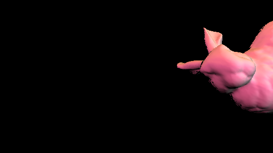
(I’m not sure what’s up with those black spots at the edges. It could be a precision thing, like z-fighting? a backface culling error? the same spots are white in the z-buffer. maybe it’s do do with very narrow faces and precision with the edge function?)
Comments