originally posted at https://canmom.tumblr.com/post/160128...
So before we talk about texture coordinates, I made a render of the Stanford Dragon, which has about 800,000 triangles. My renderer did it in a few seconds, which was pretty sweet.
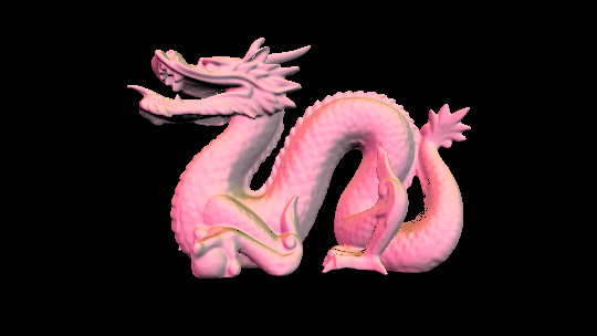
As we’ll discuss later in a sec, the vertex normals here are incorrectly interpolated, which is probably the cause of the black dots.
Also of note is the unfortunate saga of libpng. Since this ultimately had almost no effect on the final project, I won’t discuss it here.
Fixing my botched implementation of perspective-correct interpolation
As I noted in a recent post, I made a very silly algebraic mistake in my determination of how to use the NDC z coordinate in the calculation of perspective-correct interpolation.
I made an attempt to fix the mistake, but convinced myself it was still wrong (in fact the problem was unrelated). So I decided to have another go at finding out how OpenGL does it.
In fact, the information is available after all, indeed it’s in the OpenGL spec. The calculation is described here. In short, openGL does not use the value I’ve been calling \(z_\text{ndc}\) in perspective interpolation, but instead makes use of the fact that in clip space, the \(w\) coordinate is equal to -z, and keeps the value of \(\frac{1}{z}\) around in the \(w\) coordinate.
In the spirit of imitating OpenGL, I’m also going to remove the passing of camera space (non-projected) coordinates which are used to calculate the face normal, and rely purely on interpolation of vertex normals. I will, however, add a function to recalculate face normals for flat shading.
That means I will need to change my implementation of backface culling, which is currently based on the z component of the face normal. OpenGL actually does this in terms of winding order in screen space. But how is this determined? After some poking, it apparently depends on the signed area of the polygon in window space, which Wolfram MathWorld gives as $$\Delta=\frac{1}{2}(-x_2 y_1+x_3 y_1+x_1 y_2-x_3 y_2-x_1 y_3+x_2 y_3)$$and for a general \(n\)-vertex polygon, someone says an OpenGL book gives it as $$\Delta = \frac{1}{2} \sum_{i=0}^{n-1} \left(x_i y_{i+1\bmod n} - x_{i+1\bmod n} y_i\right)$$and MathWorld gives an equivalent definition.
So let’s write a signedarea function (after checking GLM doesn’t have one, and it doesn’t seem to)…
float signed_area_2d(const array<vec4,3>& v) {
    //calculate the signed area of a triangle in the xy plane
    //the arguments are vec4 not vec2 for convenience, but only xy coordinates are relevant
    return 0.5f*(
        v[0].x * v[1].y - v[1].x * v[0].y +
        v[1].x * v[2].y - v[2].x * v[1].y +
        v[2].x * v[0].y - v[0].x * v[2].y)
}
I flipflopped on including the 0.5f factor, but I thought it would be best to have the function do what it says it does, even if it involves an extra multiplication per face (per-face operations are not a major bottleneck, in any case, compared to per-fragment operations).
Later, a backface culling vs. normals problem cropped up that revealed I’d apparently got the signs the wrong way round, probably due to an implicit reflection in having the camera pointed along the negative z axis or something? I don’t really know. In any case, I had to whack a minus sign in there.
Passing values to this function involved a substantial rewrite of all my drawing functions. The result, at least, though it isn’t by any means compliant with the OpenGL standard, now fairly closely follows the steps in the OpenGL pipeline except for clipping, and some of the functions I’ve written can be identified with shaders for the OpenGL pipeline.
Interpolating texture coordinates
In fact the texture coordinates themselves are very easy to handle: unlike normals and vertex coordinates which require geometric transformations from model space before they can be used, texture coordinates can be used as is.
Generating the texture coordinates - a step termed UV mapping by 3D artists - is another story. There are lots of tutorials on UV mapping out there, so I’m not going to go into how you make a good UV map (I don’t really know anyway); the important part is that you can edit a UV map in Blender, and export the texture coordinates in an Obj file.
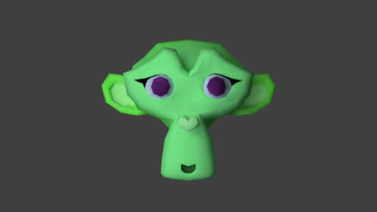
So I unwrapped Suzanne, and painted a simple texture in Blender. Here’s a quick render in Cycles, which is the powerful raytracer that Blender uses.
I decided to make my own limited Material class rather than use tinyobjloader’s material_t, since I wanted to include pointers to textures in the class.
class Material {
private:
  glm::vec3 diffuse_colour; //r, g, b albedo values
  bool has_texture;
  std::string diffuse_texture_file; //path to diffuse texture
  cimg_library::CImg<float> diffuse_texture;

public:
  Material(const glm::vec3 & dc) : diffuse_colour(dc), has_texture(false) {}
  Material(const glm::vec3 & dc, const std::string & dtf) : diffuse_colour(dc), has_texture(true), diffuse_texture_file(dtf), diffuse_texture(diffuse_texture_file.c_str()) {
    diffuse_texture.normalize(0.f,1.f);
  }
  glm::vec3 sample(const glm::vec2 & uv) const;
};
To implement the sampling function, I took advantage of the linear interpolation fuctions in the CImg library:
vec3 Material::sample(const vec2 & uv) const {
  if (has_texture) {
    float u = uv.x * diffuse_texture.width();
    float v = (1.f-uv.y) * diffuse_texture.height();
    return vec3(diffuse_texture.linear_atXY(u,v,0,0),diffuse_texture.linear_atXY(u,v,0,1),diffuse_texture.linear_atXY(u,v,0,2));
  }
  else {
    return diffuse_colour;
  }
}
In principle, the UV coordinates should never be negative, or greater than 1. However, inevitable floating point precision errors can sometimes make them very slightly so. Fortunately the CImg linear interpolation functions automatically handle this with ‘Dirichlet boundary conditions’, meaning if the values of u and v are out of bounds, the value of the nearest pixel will be used instead.
The triangle needed to be extended to include an index into a list of materials. (Since the materials are not transformed, I could equally well have used a pointer or reference, but this is the convention I was using for the other values, and makes it easy to load the files).
struct Triangle {
  //indices into vectors of coordinates, vertex normals, and uv texture coordinates for each vertex
  std::array<int,3> vertices;
  std::array<int,3> normals;
  std::array<int,3> uvs;
  int material;
  Triangle(std::array<int,3> v, std::array<int,3> n, std::array<int,3> uv, int m) : vertices(v), normals(n), uvs(uv), material(m) {};
};
At some point I got it into my head that it would be better to use STL arrays instead of uvec3s or ivec3s for the other indices. I’m not sure what difference I thought this would make now. I think I believed that you could only index vec3s with the x, y, z properties which would obscure the meaning of these collections, but in fact, you can use [i] just as easily. STL arrays were still useful for arrays of vectors, but here it might have been better not to bother.
With this representation in hand, I was able to update the file loading function… and make a bunch of mistakes. First, I accidentally ended up stepping through the list of material indices for each face three at a time because I tried to be clever and made a mistake, and therefore wrote random bits of memory as if it was vertex coordinates, which inevitably led to a segfault later. Second, I accidentally loaded vertex normal components as if they were UV coordinates. Both took ages to work out what was going wrong, and neither was particularly my finest moment.
Eventually, I got there. You can see the cleaned up code here.
I also set up the main renderer.cpp and drawing functions to load UV coordinates and materials. This actually took place before the above described rewrite of perspective-correct interpolation, but I’ll describe both in combination.
First, excerpting the code for backface culling:
//use signed area to determine whether the face is a front or back face
float face_raster_signedarea = signed_area_2d(face_raster_vertices);
//if wind_clockwise is set, a negative value is a front face, otherwise a positive value is
bool front_face = (face_raster_signedarea > 0) xor wind_clockwise;

if (front_face) { //backface culling
Second, I am now storing \(\frac{1}{z}\) values in the \(w\) coordinate of the raster_vertices, comparable to gl_fragcoord. This is accomplished due to a revised function for the z-divide:
vec4 z_divide(const vec4& clip_vertex) {
    //take 4D vector clip_vertex in homogeneous coordinates and return equivalent of gl_fragcoord
    //the first three coordinates are the equivalent 3D vector, and the fourth is 1/w
    return vec4(
        clip_vertex.x/clip_vertex.w,
        clip_vertex.y/clip_vertex.w,
        clip_vertex.z/clip_vertex.w,
        1.f/clip_vertex.w
    );
}
Third, the pixel-drawing function has been substantially revised to make the method of perspective-correct interpolation clearer and perhaps a little faster.
inline vec3 interpolation_coords(const vec3 & inverse_depths, const vec3& bary) {
    //calculate the elementwise products of inverse depths and barycentric coordinates and store it in inter_coords

    return inverse_depths * bary;
}

template <typename T>
inline T perspective_interpolate(const array<T,3> & vert_values, float depth, const vec3 & interpolation_coords) {
    //perspective-correct linearly interpolate or extrapolate a quantity v defined on three vertices in screen space
    //the interpolation coordinates are the products of inverse camera space depths and barycentric coordinates
    //the depth should be the inverse of the sum of the interpolation coordinates
    //bary should contain barycentric coordinates with respect to the three vertices

    return depth * (
        interpolation_coords[0] * vert_values[0] +
        interpolation_coords[1] * vert_values[1] +
        interpolation_coords[2] * vert_values[2]);
}

void update_pixel(unsigned int raster_x, unsigned int raster_y,
    const array<vec4,3>& raster_vertices,
    const array<vec3,3>& vertnormals, const array<vec2,3>& vertuvs,
    const vector<Light>& lights, const Material& material,
    CImg<unsigned char>& frame_buffer, CImg<float>& depth_buffer,
    bool wind_clockwise) {
    //take pixel at point raster_x,raster_y in image plane
    //determine if it is inside triangle defined by raster_vertices
    //if so, determine if it is nearer than the current depth buffer
    //if so, update depth buffer and shade pixel

    //determine the barycentric coordinates of this point
    vec3 bary = barycentric(vec2(raster_x,raster_y),raster_vertices);

    //Is this pixel inside the triangle?
    if (glm::all(glm::greaterThanEqual(bary,vec3(0.f)))) {

        //depth buffer algorithm:
        //determine the Normalised Device Coordinate depth value
        array<float,3> ndcdepths = {raster_vertices[0].z,raster_vertices[1].z,raster_vertices[2].z};
        float ndcdepth = screen_interpolate(ndcdepths,bary);

        //Is this pixel nearer than the current value in the depth buffer?
        if(ndcdepth < depth_buffer(raster_x,raster_y)) {
            //update the depth buffer
            depth_buffer(raster_x,raster_y,0,0) = ndcdepth;

            //interpolation of values on vertices:
            //determine the perspective-correct interpolation coordinates (barycentric divided coordinates by camera space depth of that pixel)
            vec3 inter = interpolation_coords(vec3(raster_vertices[0].w,raster_vertices[1].w,raster_vertices[2].w),bary);

            //determine the camera-space depth of the point:
            float depth = 1.f/(inter[0]+inter[1]+inter[2]);

            //interpolate vertex normals
            vec3 normal = glm::normalize(perspective_interpolate(vertnormals, depth, inter));
            if (wind_clockwise) {normal = -normal;}

            //interpolate uv coordinates
            vec2 uv = perspective_interpolate(vertuvs, depth, inter);

            //work out what colour this pixel should be (in OpenGL terms, run the fragment shader)
            uvec3 pixel = shade(
                normal,
                material.sample(uv), //if there is a texture, use the texcoord-appropriate colour
                lights);

            //update the frame buffer with the new colour
            frame_buffer(raster_x,raster_y,0,0) = (unsigned char)pixel.r;
            frame_buffer(raster_x,raster_y,0,1) = (unsigned char)pixel.g;
            frame_buffer(raster_x,raster_y,0,2) = (unsigned char)pixel.b;
        }
    }
}
Here I’m multiplying of the 1/z value defined in the w coordinate by the barycentric coordinates to make whta I’m calling 'interpolation coordinates’, which can be reused for every quantity we might need to interpolate. While this is not much of a gain when we’re only interpolating two quantities, in general it could be quite useful and it’s closer to what I understand of how OpenGL handles it.
The results
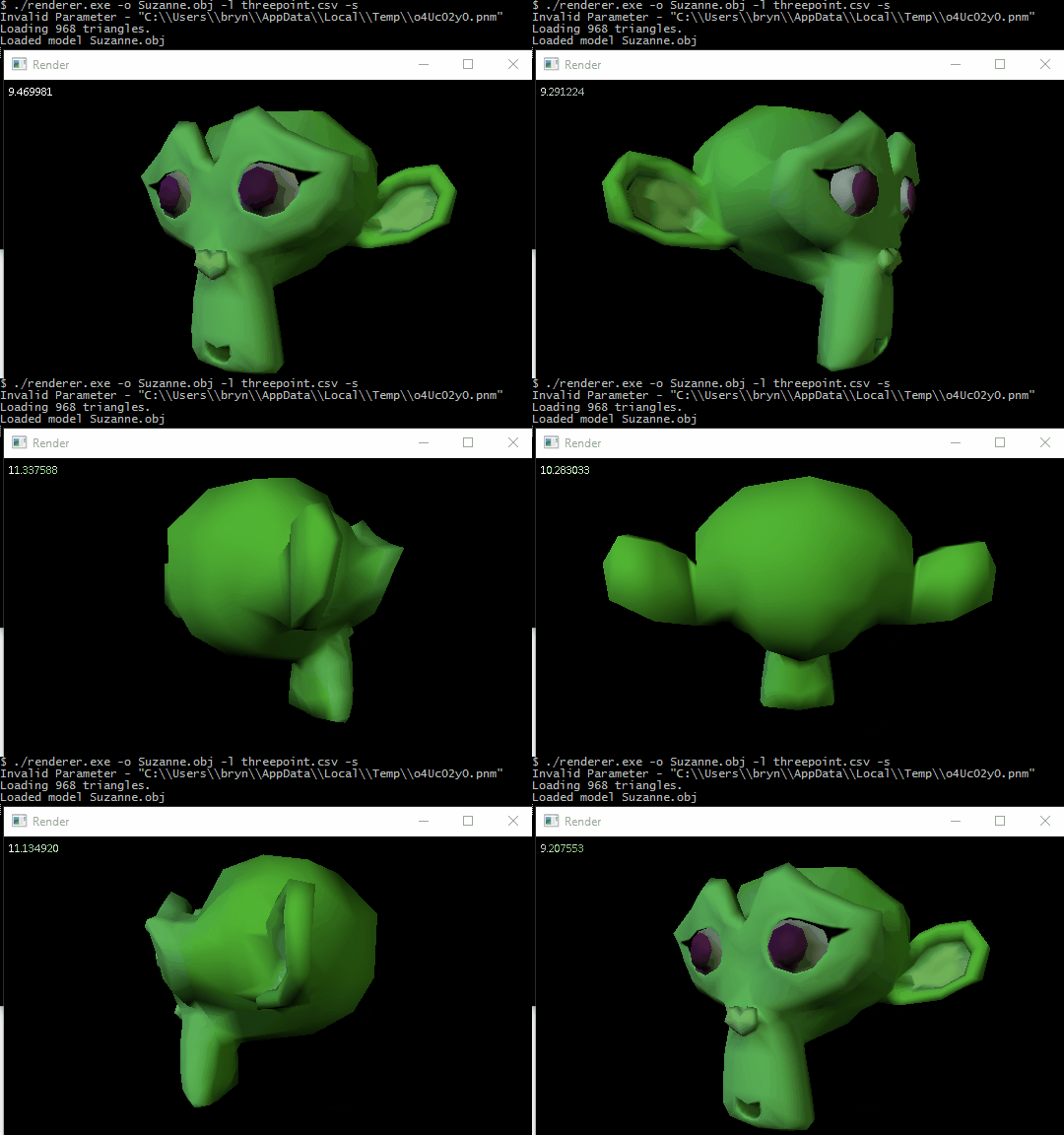
I’ve spoiled you by posting this yesterday, but check this out:
We can also re-render the bunny and see if we managed to fix the black dots issue…
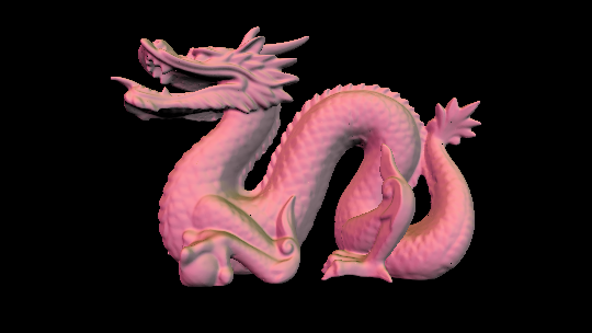
That actually changed the shading quite a lot! It looks uglier, though that could probably be fixed by redesigning the lights, which were set up with the wrong interpolation function in mind. It should be considerably more accurate. We’re still getting the occasional black dot, but in different places, and I’m not entirely sure what’s causing them there.
And, for good measure, let’s try it with a model from Pokémon X and Y with a few different textures…
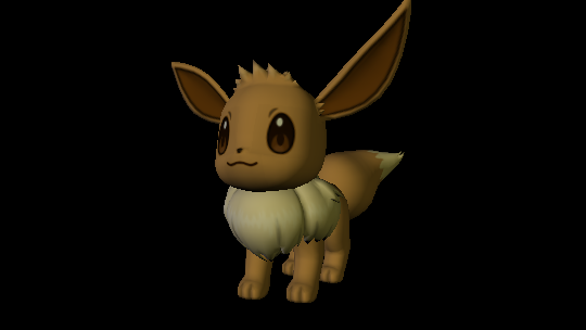
This required a bit of fiddling, because the Eevee model actually has its UV coordinates for the eyes and mouth mapped out of bounds, on the assumption that the image will tile endlessly? Which, in fact, is the way games must generally handle it, thinking about how often you see tiling textures which could be achieved just by making the vertex UV coordinates out of bounds… ah well. Maybe at some point I’ll look into rewriting the sampling function.
The model actually got like 100fps when rotating, which I didn’t expect at all. I guess it takes up less of the screen than Suzanne, and that’s less important than how many triangles it has?
What now?
With that, this project is essentially finished! I’m there!
I could try to implement more things, but at this point it’s definitely time I moved on to writing shader code to use with OpenGL itself. (Or Vulkan). I’m not entirely sure what the next project is going to be, but I plan to use OpenGL or WebGL in it.
I really hope you enjoyed this whole series! I’m really satisfied, I definitely feel like I’ve learned a lot about how 3D graphics really work, and like, I’m super proud of the result?
Comments