originally posted at https://canmom.tumblr.com/post/159127...
Tidying up a bit
I’m sure typing glm::vec3 a lot, right? It occurred to me that I should import some of the commands I’m using a lot into the global namespace with a using directive.
using std::vector;
using std::cout;

using glm::vec3;
using glm::vec4;
using glm::mat4;
That lets me remove a lot of cluttered std:: and glm:: stuff, making the code more readable.
All is change
OK, so in the last post, we made a function to calculate the camera matrix. The algorithm now calls for us to multiply every vertex by the camera matrix, producing a new set of coordinates in clip space. In actual OpenGL, a clipping algorithm would then cut down triangles outside of the viewing frustum, but if we implement that in this toy software renderer, it won’t be until later.
Now we need to go and apply that matrix to every item. The simplest way would be to instantiate a new vector object, apply the transformation function to each point, and then use push_back to put it into the vector. However, I got a bit of a premature optimisation thing into my head, and thought that’s going to require us to repeatedly resize the vector unnecessarily, and allocate memory for a temporary vector inside the function, and wouldn’t it be easier just to copy it into an existing vector?
The C++ standard library, it turns out, has a way to apply a function to every element of an iterable and store it in a new iterator: the transform function defined in the <algorithms> standard library header file. This requires our transformation to be a unary operator.
Awkwardly, our transform function, however it works, depends on a potentially-changing camera matrix, so it’s a binary operator. What we need to do is a partial function application. C++ is not a functional language, but in C++11, there is a library with some functional stuff, including partial application, suitably named <functional>.
Honestly, partial application the ‘transform’ function are premature optimisation for what I’m doing (at best, they arguably make the code easier to read), but I was curious to try it out and see if I can get it to work.
Here are the new programs and includes…
#include <algorithm>
#include <functional>

using namespace std::placeholders;

vec4 transform_point(const mat4& transformation, const vec3& point) {
    vec4 homo_point(point.x,point.y,point.z,1.0f);
    return transformation * homo_point;
}

void transform_vertices(const mat4& transformation, const vector<vec3>& vertices, vector<vec4>& result) {
    result.resize(vertices.size());

    //partially apply the transform_point function with the given transformation matrix
    auto tp = std::bind(transform_point, transformation, _1);

    //apply the transformation to every point and store the results in 'result'
    std::transform(vertices.begin(),vertices.end(),result.begin(),tp);
}
Applying this to our origin-centred unit square (with the camera rotated about the origin by one radian) gives us…
-0.366864,-1.20711,0.9468,1.0792
0.366864,-1.20711,1.8463,1.92074
-0.366864,1.20711,0.9468,1.07926
0.366864,1.20711,1.8463,1.92074
This has not yet had the z-divide performed, so these are homogeneous coordinates in clip space, and their x and y values still lie on a square. But it’s easy to write a function to do the z-divide and put them in Normalised Device Coordinates:
vec3 z_divide(const vec4& clip_vertex) {
    return vec3(
        clip_vertex.x/clip_vertex.w,
        clip_vertex.y/clip_vertex.w,
        clip_vertex.z/clip_vertex.w
    );
}

void z_divide_all(const vector<vec4>& clip_vertices, vector<vec3>& ndc_vertices) {
    ndc_vertices.resize(clip_vertices.size());

    std::transform(clip_vertices.begin(),clip_vertices.end(),ndc_vertices.begin(),z_divide);
}
So what are normalised device coordinates, exactly?
In OpenGL, normalised device coordinates cover a [1,-1] cube. The x and y coordinates correspond orthographically to the positions of each vertex on the screen, while the z coordinate is a monotonic function of the vertex’s original distance from the camera.
This means that if we take our NDCs from the program, and plot them in the xy plane (rescaling appropriately for the aspect ratio), we’ll see where they’ll be in our render.
Here are our points:
-0.33992,-1.11845,0.877264
0.191002,-0.628461,0.961248
-0.33992,1.11845,0.877264
0.191002,0.628461,0.961248
Already we can see they have the symmetries we’d expect. Concerningly, some of the coordinates are larger than 1, suggesting we’ve put our camera too close to the subject. For an \(M \times N\) display, we can remap to the final display coordinates with \begin{align}x_\text{display}&=\frac{M}{2}(x_\text{ndc} + 1)\\y_\text{display}&=\frac{N}{2}(y_\text{ndc} + 1)\end{align}Note that we assumed a 16:9 aspect ratio in our calculation of the perspective matrix, so M:N should have the same ratio.
Although this isn’t actually how the rasterisation algorithm works, let’s write a temporary function to convert from NDC to display coordinates and print them out, ignoring the z value.
vec2 print_display_coords(const vec3& ndc_vertex, const float& display_width, const float& display_height) {
    cout << 0.5f*(ndc_vertex.x+1.0f) * display_width << ',' << 0.5f*(ndc_vertex.y+1.0f) * display_height << '\n';
}
Mapping this function over our square’s vertices gives us…
5.28064,-0.533039
9.52801,1.67193
5.28064,9.53304
9.52801,7.32807
We can plot these points with any plotting program. For example, with Mathematica, it comes out as…
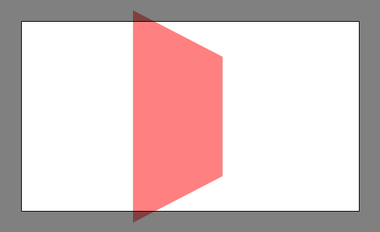
(The black border will not be rendered. And was an absolute pain to work out how to draw, but it turns out FilledCurve does the trick.)
This does indeed look like it could be a square in perspective, but is it correct? We can recreate the scene in Blender. Placing a plane and the camera at the right scales and rotating the camera by a radian is easy. The tricky part comes with picking the field of view of the camera. Blender specifies the camera’s horizontal field of view, while OpenGL specifies the vertical. We thus need to perform some trigonometry. For an \(M\times N\) screen, a horizontal field of view \(\theta_h\), and a vertical FOV \(\theta_v\), this comes out as $$\theta_h = 2 \arctan \left( \frac{M}{N} \tan \frac{\theta_v}{2} \right)$$Thus with our vertical FOV of 45° we find the horizontal FOV to be 72.73°.
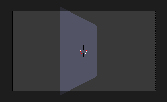
And as it turns out, our perspective calculation was right on the money! Which is satisfying.
So that’s the coordinate transformations working just as we want them (except perhaps for normals, but that will come later). Next is the actual rasterisation part, where the triangles in our scene are converted into pixels.
Comments