originally posted at https://canmom.tumblr.com/post/159235...
Perspective correct z-interpolation
At the end of the last post, I wrote a template function that interpolates values defined at the vertices using barycentric coordinates. I tested it with floats and vec3s and it seems to work just fine in both cases, which is nice! This is the first time I used templates, so, I wasn’t sure.
Unfortunately, as the next two chapters on scratchapixel discuss, such simple interpoloation is not perspective correct for general triangle vertex properties, or for depth (due to the perspective transform into NDCs being nonlinear). Well, that’s unfortunate!
For depth, it turns out we have to interpolate the inverse of the depth of the vertices, and then invert it. The geometric derivation is pretty interesting! I wanted to go through it myself, with more familiar notation. This is going to be functionally the same derivation as on Scratchapixel, just expressed in different words.
So here’s our setup: there’s a line in the \(x\)-\(z\) plane. It is projected to a line in the image plane, which is parallel to the \(x\) axis. We take a general point \(\mathbf{v}\) with coordinates\((x,z)\), which we can express parametrically in terms of the endpoints \(\mathbf{v}_0\) and \(\mathbf{v}_1\) as $$\mathbf{v}=\mathbf{v}_0 + t (\mathbf{v}_1-\mathbf{v}_0)$$for some parameter \(t\) in the range \([0,1]\).
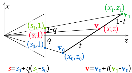
We project these three points into the image plane, which we’ll take to have \(z\) coordinate 1 (wlog). We’ll define \(s\) as the \(x\)-coordinate the projection of \(\mathbf{v}\). By similar triangles, this means $$s=\frac{x}{z}$$which is the familiar perspective \(z\)-divide.
We also say that the projected point varies with another parameter \(q\) such that $$s=s_0+q(s_1-s_0)$$In the situation of the renderer, \(q\) corresponds to the screen space barycentric coordinates, and our problem arises from the fact that \(q\) is only proportional to \(t\) when the line in 3D space is parallel to the image plane.
In the example used in Scratchapixel, they’re not using the OpenGL perspective projection matrix, and they haven’t remapped \(z\) into Normalised Device Coordinates. Let’s consider that situation first, then I’ll see how to adapt it to our OpenGL-imitating case.
So we want an expression that gives us \(z\) in terms of \(z_i\) and \(q\) without reference to any \(x_i\) or \(t\).
Let’s start by expanding the relation for \(s\): $$\frac{x}{z}=\frac{x_0}{z_0}+q\left(\frac{x_1}{z_1}-\frac{x_0}{z_0}\right)$$We can also substitute the formula for \(x\) as an interpolation between two points into this equation: $$\frac{1}{z}(x_0+t(x_1-x_0))=\frac{x_0}{z_0}+q\left(\frac{x_1}{z_1}-\frac{x_0}{z_0}\right)$$Now, let’s group the terms in \(x_0\) and \(x_1\): $$x_0\left(\frac{1-t}{z}+\frac{q-1}{z_0}\right)+x_1\left(\frac{t}{z}-\frac{q}{z_1}\right)=0$$
In general, \(x_0\) and \(x_1\) are arbitrary, but this equation must be true regardless. This requires that their coefficients vanish identically (I think. Mathematicians challenge me if that logic is shaky!). Taking the second of these coefficients and setting it equal to 0 gives us $$t=\frac{zq}{z_1}$$which we can substitute into the first one to get $$\frac{1}{z}=\frac{1-q}{z_0}+\frac{q}{z_1}$$This is precisely the formula that Scratchapixel got, and we don’t have to process a giant block of algebra (though I’m not sure if it’s less conceptually opaque).
So all we need to do is interpolate 1/z.
What about the projection matrix?
But hold on… as we alluded to above, the z-values of our points projected using the OpenGL projection matrix into Normalised Device Coordinates are not the same as the z-values of the original points in world space. In fact, I think we’ve already done some of the work in using that matrix.
Let’s look at the OpenGL perspective projection matrix again. Since we’re using a symmetric perspective matrix defined in terms of the FOV, near clipping plane distance \(n\) and far clipping plane distance \(f\), and aspect ratio \(a\), we can simplify the formula to $$\begin{pmatrix}
{ \dfrac{1}{a\tan(\mathrm{fov}) } } & 0 & 0 & 0 \\
0 & { \dfrac{1}{\tan(\mathrm{fov})} } & 0 & 0 \\
0 & 0 & -{\dfrac{f+n}{f-n}} & -{\dfrac{2fn}{f-n}}\\
0 & 0 & -1& 0\\
\end{pmatrix}$$
As a reminder, this matrix projects points in 3D space into clip space, which uses a four-coordinate vector in homogeneous coordinates. This has a \(w\) coordinate equal to negative the original \(z\) value of our point (i.e. its distance to the camera). We then go back to homogeneous coordinates normalised such that \(w=1\) by dividing this vector by its \(w\) coordinate, which puts us in Normalised Device Coordinates.
What does this do to the \(z\) coordinate? Well, in clip space, we get a value of $$z_\text{clip} = -\frac{f+n}{f-n}z - \frac{2fn}{f-n}$$ and once this gets divided by \(w_\text{clip}=-z\) we end up with $$z_\text{ndc}=\frac{f+n}{f-n}+\frac{2fn}{f-n} \frac{1}{z}$$
Hmm. An inverse \(z\)..? Let’s try something: what happens if we add two such coordinates together in the way of the formula above? We get \begin{align} (1-q)z_\text{ndc0} + qz_\text{ndc1}&=(1-q)\frac{f+n}{f-n}+(1-q)\frac{2fn}{f-n} \frac{1}{z_0}+q\frac{f+n}{f-n}+q\frac{2fn}{f-n}\frac{1}{z_0}\\
&=\frac{f+n}{f-n}+\frac{2fn}{f-n}\left(\frac{1-q}{z_0}+\frac{q}{z_1}\right)\\
&=\frac{f+n}{f-n}+\frac{2fn}{f-n}\frac{1}{z}\\
&=z_{ndc}\end{align}
So it turns out that by using the openGL perspective matrix earlier, we’re already interpolating the depth (or rather, inverse depth plus a constant) correctly! That’s pretty sweet. And explains something I was wondering, which is why it’s necessary to project the \(z\) value into NDCs as well as the \(x\) and \(y\) values. (Still not sure why it’s not sufficient to simply invert them.
As far as the \(z\)-buffer algorithm is concerned, we’re already sorted: \(z_\text{ndc}\) is a monotonic function of \(z\) between \(z=-n\) and \(z=-f\). (Why the minuses? The camera is pointing in the -z direction.)
How to store the z-buffer and frame buffer?
So as we process our pixels, we’ll need to store the data in buffers, and ultimately write it out as an image.
The simplest way would be to simply instantiate an array. But image processing is a well-solved problem, so let’s just use a library and let the library handle all the things like, outputting images. CImg looks promising! …but it’s not on Conan. So I’ll search for “image”. ImageMagick isn’t on Conan. OpenCV is on Conan, but seems like overkill for what I want. An SDL image library is on Conan, but seems to require more of SDL to represent images, and honestly if I’m using SDL I might as well use OpenGL itself lol? FreeImage is on Conan! But… the prebuilt modules require me to be compiling in Visual Studio, not MinGW. Well, I can call the –build freeimage option on Conan and get it to try and build the package with my silly MinGW situation. But that fails! Ugh. I tried setting up OpenCV but it’s massive.
Fine, I’ll just download CImg manually and put it in like, idk, a vendor folder or something. Bluh. At least the license allows redistribution like that.
NDCs to Raster Space
I get the impression (especially since the Scratchapixel people do it in their rasteriser implementation) that it’s better to convert the vertices into raster space (i.e. the coordinate system of the final image) than to convert pixel coordinates into NDCs when we’re testing whether a pixel lies within a triangle. That’s easy enough:
vec3 ndc_to_raster(int width,int height,const vec3& ndc_vertex) {
    return vec3(
        0.5f*(ndc_vertex.x+1.0f)*width,
        0.5f*(-ndc_vertex.y+1.0f)*height,
        ndc_vertex.z);
}
Why the minus sign in the y coordinate? In the image representation in CImg (and most image representations), the \(y\) coordinate goes downwards from the top of the image, not up from the bottom! So we need to invert it.
Bounding, bounding, bounding, bounding
A simple optimisation described on Scratchapixel is not to test and shade every pixel in the image, but merely those inside the bounding box of a triangle. A bounding box can defined by the top left and bottom right coordinates, in this case found by finding the minimum and maximum x and y coordinates.
The <algorithms> standard library header, which we’re already using, has functions for this:
void bounding_box(vec2& top_left, vec2& bottom_right, const vec3& vert0, const vec3& vert1, const vec3& vert2) {
    top_left.x = std::min({ vert0.x, vert1.x, vert2.x });
    top_left.y = std::min({ vert0.y, vert1.y, vert2.y });
    bottom_right.x = std::max({ vert0.x, vert1.x, vert2.x });
    bottom_right.y = std::max({ vert0.y, vert1.y, vert2.y });
}
Arguably it might be better to loop over the face only once but I’m not sure it would, and in any case, this is probably more readable.
Testing this, it produces the results you’d expect.
This post is quite long now, so I’m going to start another one for the next part: looping over the pixels within a bounding box and producing an image.
Comments