Whoops, it’s been a long time since I updated this series! More than a year, in fact.
The goal of this article is to build up some of the ‘bag of tricks’ that artists have created over the centuries to help place things in perspective. This may seem… esoteric and nerdy; it is rare to need to construct a picture this meticulously. But seeing how they work can be useful for understanding perspective.
Contents
Contents
The first trick: extending a distance along a line
Last year we were drawing a railway—the classic example of something equally spaced, receding into the distance.
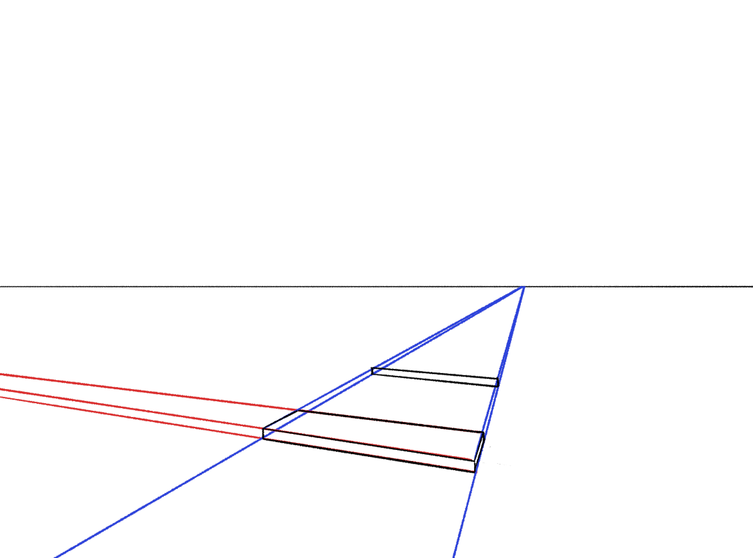
So, I want to draw all the equally distant railway sleepers, in perspective. Let’s start by drawing one sleeper.
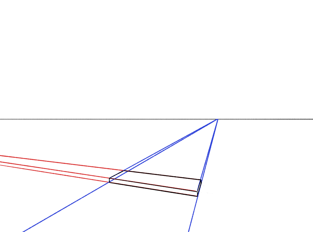
Where does the second one go? Well, that depends how far you want them to be spaced. It’s possible to work this out exactly, but for now, just eyeball it. I’m only going to draw the front plane; we’ll soon see how to work out the appropriate depth to foreshorten it anon.
Now comes the fun part. Here’s the two useful facts:
- if two things are in the same place in world space, they’re also in the same place in canvas space
- straight lines in world space are straight lines in canvas space
With that in mind, we just need to figure out the right lines to draw in order to clone our railway sleepers.
There are actually multiple approaches to this. The most common method I see is to “draw a line through the midpoint”. It goes like this…
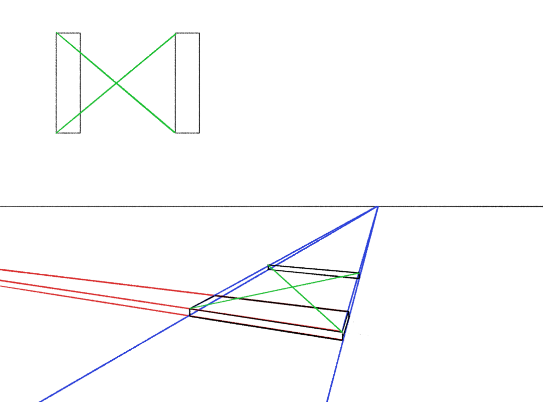
First, we find the midpoint. If we diagonally connect the corners of the sleepers, the diagonals will cross at the exact centre of this rectangle (in world space).
If we draw a line from this midpoint that’s parallel to the tracks, it will hit every single sleeper right in the middle:
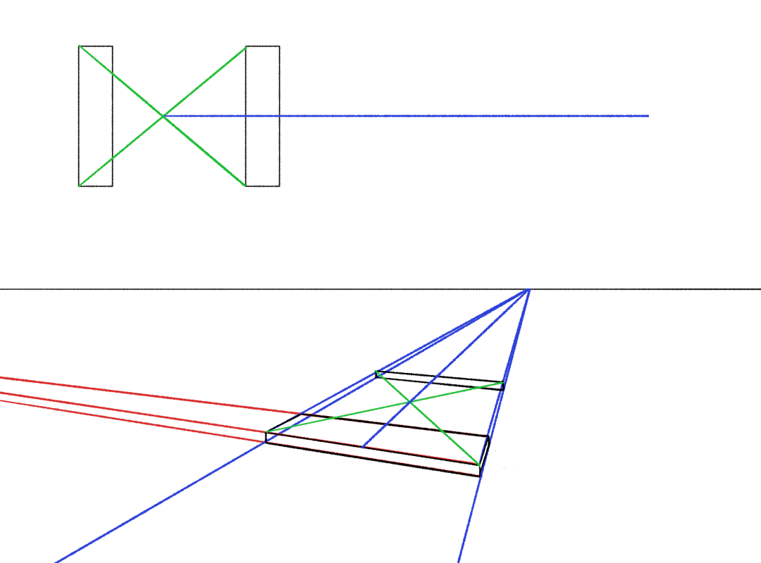
Now, if we draw a line from the edge of one sleeper through the middle of another, and then continue it to the opposite side of the track…
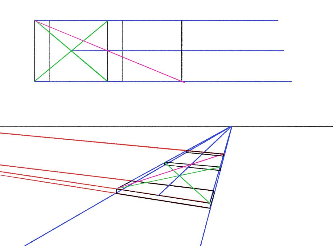
through the magic of triangles, we have cloned the distance between the sleepers!
However, there is (in my opinion) a better way! Certainly if you have access to a vanishing point tool, like in Krita. Constructing the midpoint is too laborious and restrictive.
Instead, we can simply extend one of those diagonal lines to the horizon, to find a new vanishing point for that family of diagonal lines.
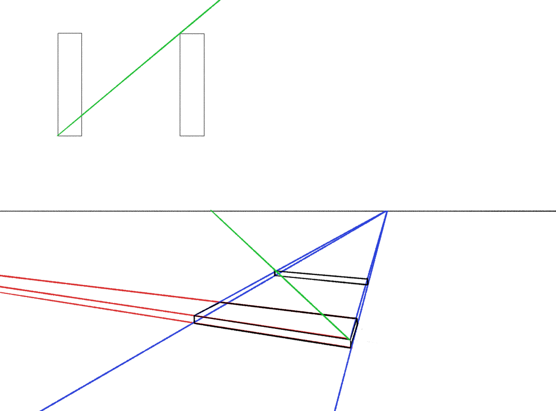
We can now connect further diagonal lines up to this vanishing point to clone the distance between the sleepers. By alternating two vanishing points, we zigzag along the track.
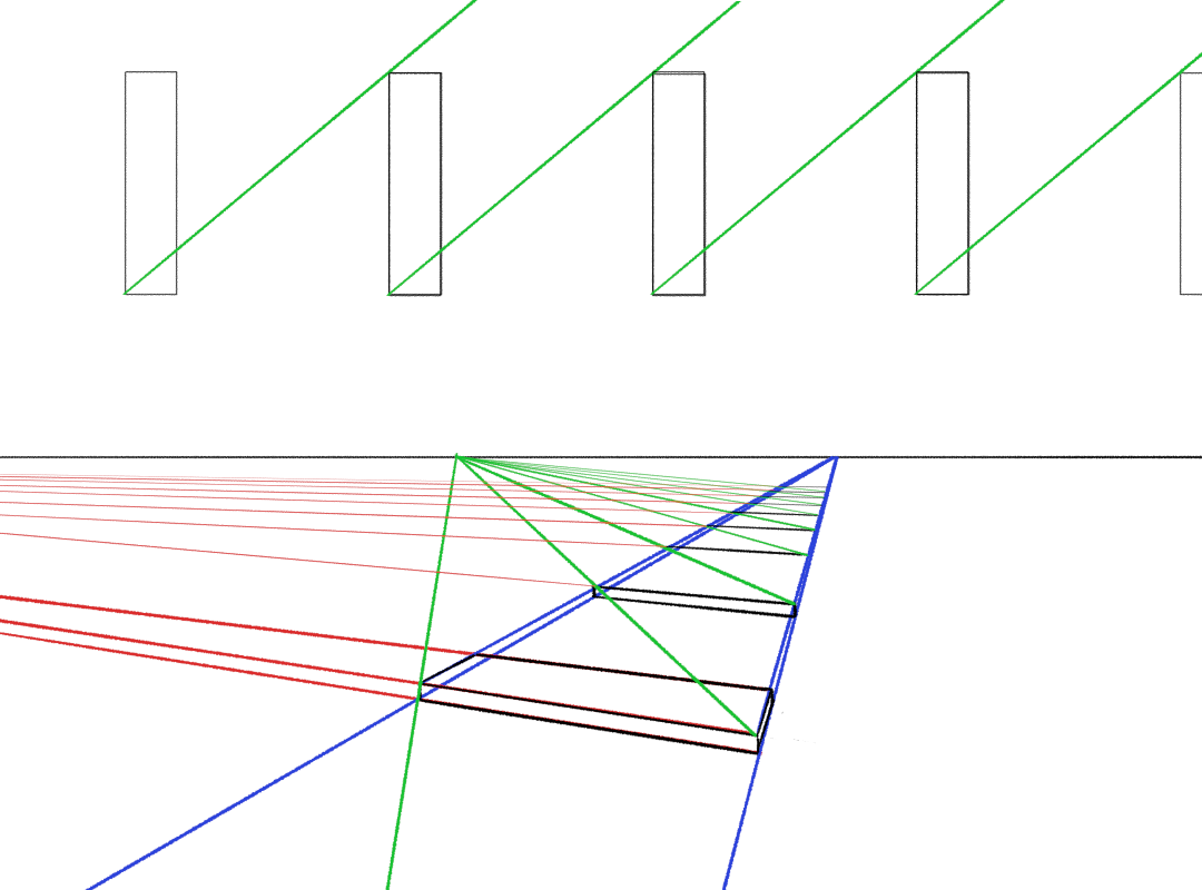
The great part about this method is that we can use it to clone any distance along a parallel line. For example, if we draw a diagonal line across a sleeper, we get another diagonal family:
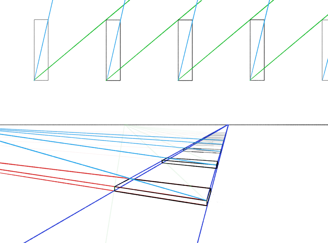
which we’ve used to foreshorten the thickness of the sleepers as they recede into the distance. The result, turning off all the vanishing line layers, is…
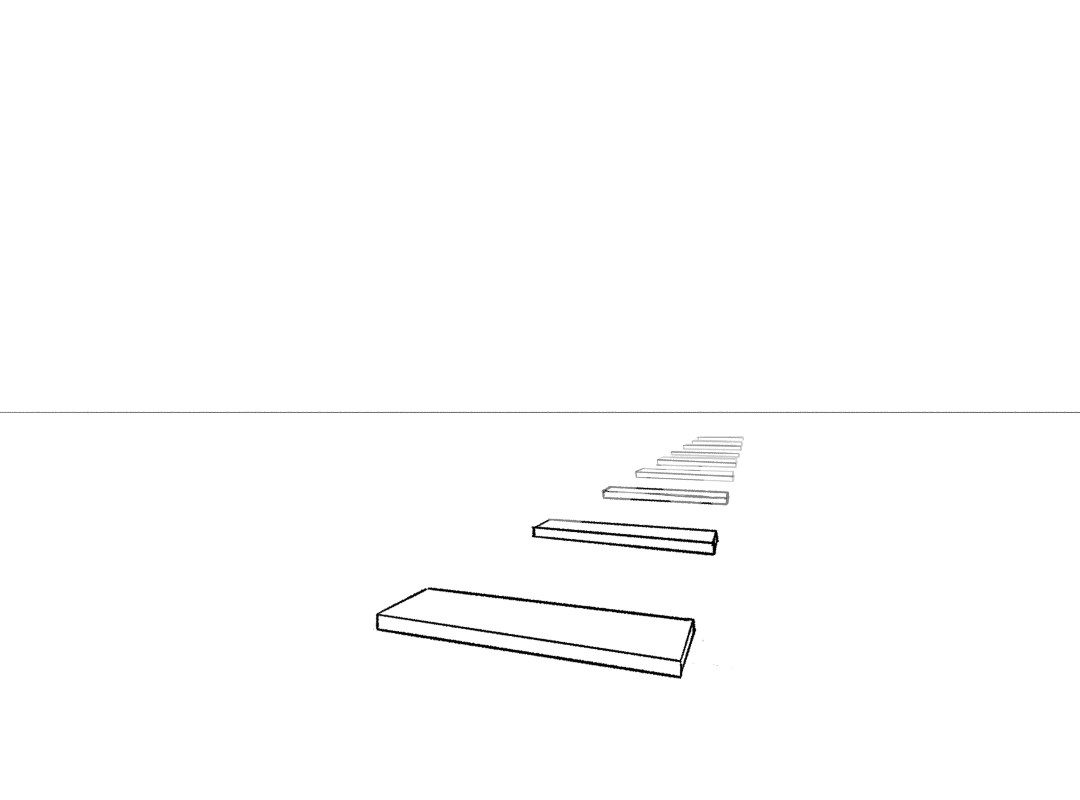
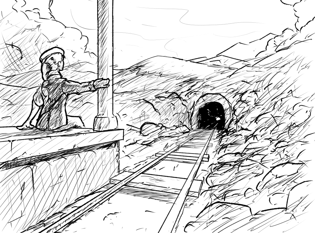
To accentuate the sense of depth, I’ve reduced the line weight and opacity of the more distant sleepers. We’ll come back to this kind of depth trick later. And for the hell of it, let’s draw the rest of a scene.
This trick is very useful if you want to clone distances. For example, in animation, if a character is walking away from the camera in perspective, and you want their steps to be evenly spaced, you can use a method like this to space out your keyframes. (Perspective walks are very difficult, though, so don’t be discouraged.)
To express this in a slightly more formal algebraic way, which you may or may not find useful depending on your inclinations:
To clone a vector in the direction it's pointing
To transport a vector (3D line segment) which we’ll call V, which has vanishing point VP1, in the direction it’s pointing:
- draw a line through V to VP1, which we’ll call L1.
- create a second line L2 that also goes to VP1 (i.e. L2 is parallel to L1 in 3D space).
- pick a second vanishing point, VP2. Connect VP1 to VP2 with a line, which we’ll call H (for Horizon).
- draw a line from VP2 through the starting point of V, up to L2. Let’s call the point where it crosses L2 I1 (for Intersection 1).
- draw a line from I through the ending point of V, and extend it all the way to H. Where it crosses H, you have the vanishing point of the ‘diagonal’ lines. We’ll call this VP3.
- pick a point on L1 where you want to copy the ending point of V. Let’s call this T for Target.
- draw a line from VP3 through T, and continue it until you hit L2. Call this point I2 (for Intersection 2).
- draw a line from VP2 to I2. This line should cross L1. The point where it crosses L1 is the starting point of the cloned line segment. Connect this to T and you’re done.
This is probably better expressed by a gif:
Cloning distances along a non-parallel line
We can extend this technique slightly to transport vectors in arbitrary directions. (It’s implicit in what we did above, but I think it’s worth showing in detail.)
To clone a vector in an arbitrary direction
To transport a vector (3D line segment) which we’ll call V, which has a vanishing point VPV, along another line L1, which has vanishing point VP1:
- draw a line from VP1 through the endpoint of V. we’ll call this line L2.
- pick a point on L1 where we want to clone V. Call this point T.
- draw a line from VPV through T until it hits L2—a point which we will call I.
- draw a line from T to I. You’re done!
Now that may seem simpler, but we had some extra information to start (two different vanishing points). The tricky part in practice may be finding the vanishing point of the vector V you’re trying to clone.
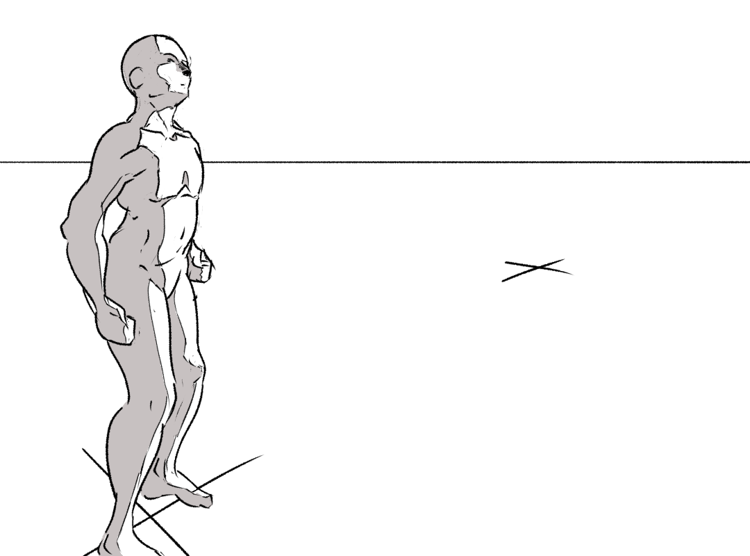
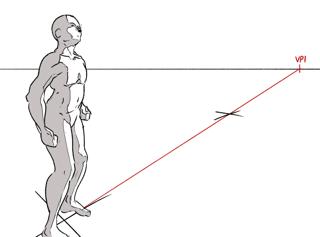
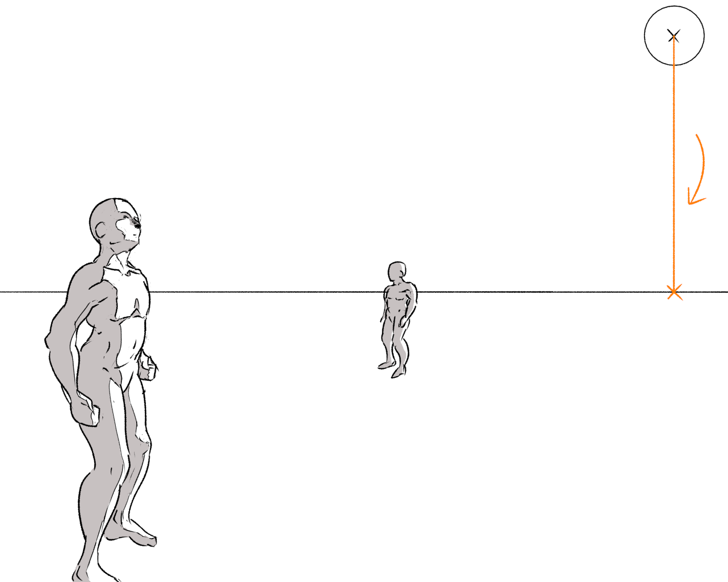
One of the most common examples is when you have multiple characters of about the same height standing on the same ground plane. For example, suppose you have a character in one spot, and you want a second character standing further from the camera at a particular spot on the ground…
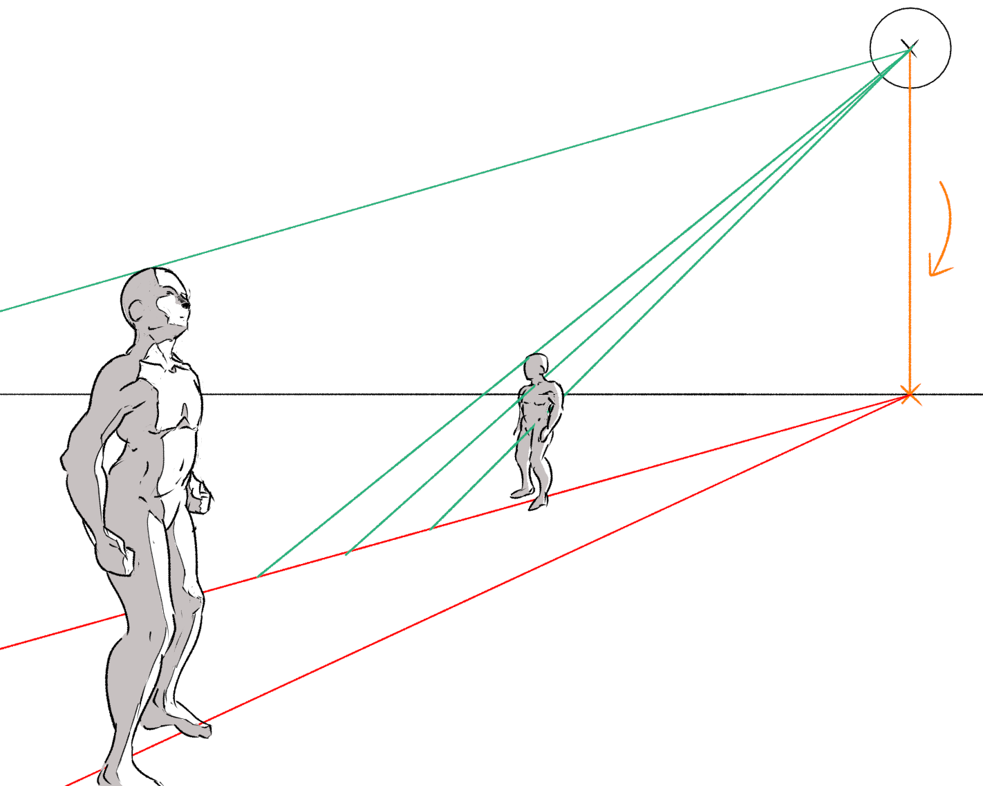
To find a vanishing point for these two figures, we can simply draw a line through the two ‘base’ points up to the horizon.
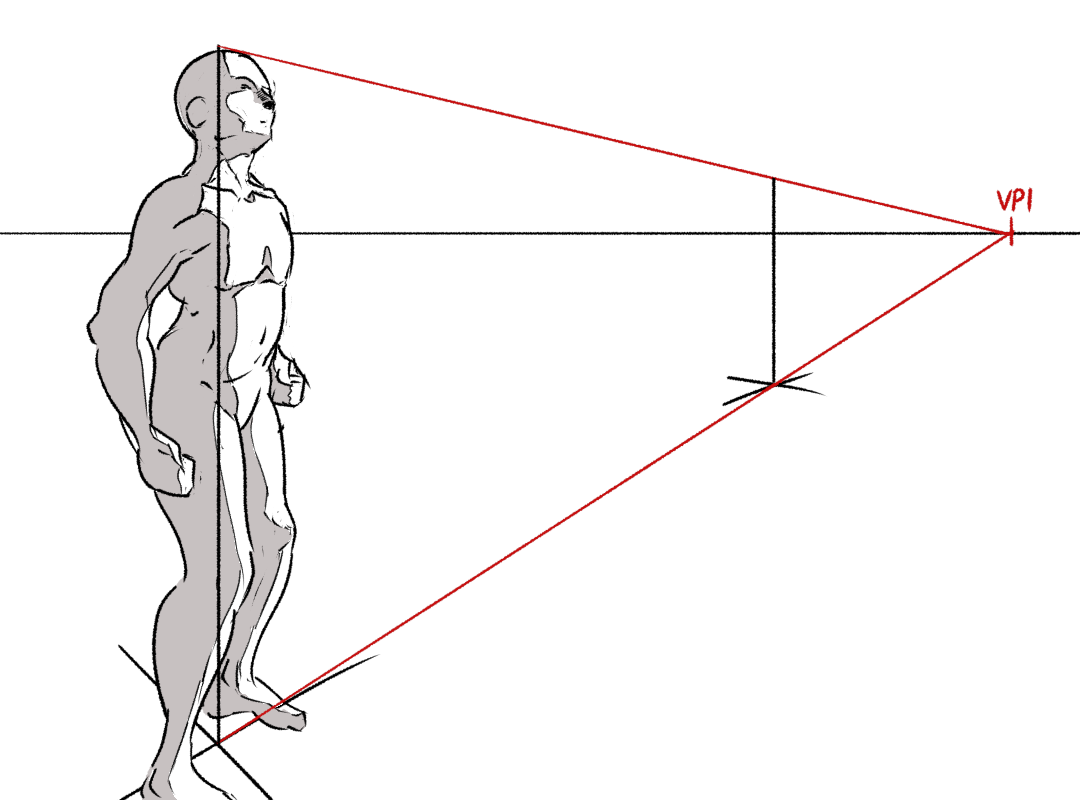
Then we can connect this to the head of the first figure, and use it to transport a line along the plane.
Then we can draw a figure to match that line.
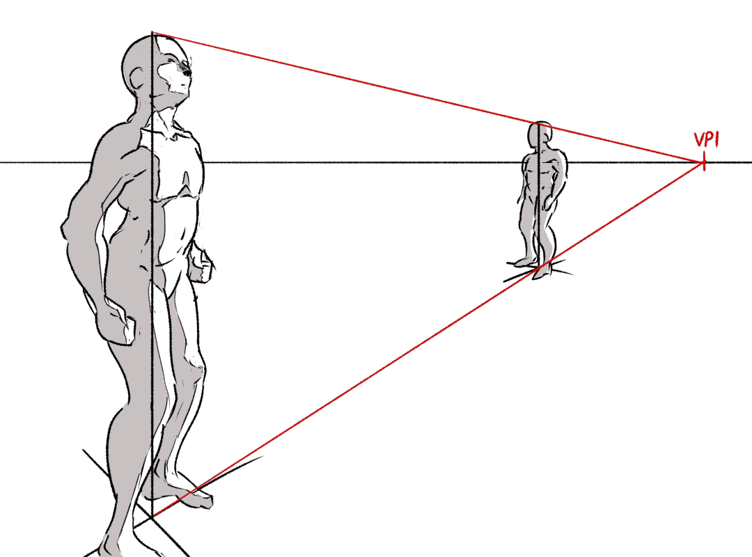
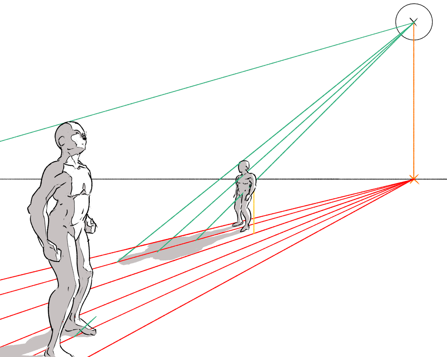
One thing that you may notice here is that the horizon line crosses both figures at about shoulder height. This indicates the height of the camera. In general, the horizon line will cross figures at the height of the camera. For an eye-level camera, it will cross the figures at eye level. This follows from geometry: the ‘eye lasers’ from the camera that run horizontal to the ground are the ones that vanish on the horizon line. So for a POV shot at eye-level, the horizon line should cross characters at around eye-level (modulo their individual heights). If the camera is placed low to the ground for a low-angle shot, the horizon line should cross near the ankles.
In this picture, to simplify as much as possible, I’ve chosen an asymmetric crop that isn’t typical of a camera, where the principal point is off-centre. This may look a little odd; we can instead choose to make the principal point central like in a camera and draw the figures with a true three-point perspective. But to know how to place the third vanishing point accurately, we’ll need to know how to use the 90-degree circle, so I’ll come back to that one next time!
The underlying method:
All of the tricks above are essentially variants of ‘building our way out’ by following chains of implications. The core ‘building blocks’ are, to me anyway,
- if we know two points, we can connect them with a line segment
- if we know a line segment lies in a plane, we can find its vanishing point by extending it to the vanishing line of the plane
- if we know a line’s vanishing point, we can create a line through any point that’s parallel to the first line
- if we know two vanishing points, we can draw a line through them to create the vanishing line of a plane containing both families of parallel lines
- if we know two lines live in same plane, their intersection in world space is the same as their intersection in canvas space
So yes, the way I’m presenting it, it is very very much like constructing a mathematical proof: you have a set of ‘allowed moves’, a thing you want to find, and a starting list of ‘axioms’ (the points and lines you already know).
Using these tricks, you can construct a perspective grid without the aid of a computer. (You should, however, probably use a computer!) Here’s a quick gif I made a little while ago to illustrate how you’d do this:
Casting shadows
These two figures in their white void have form shadows, but to really anchor them in the scene, they ought to be casting shadows as well. How do we work out where to put a shadow in perspective?
The general method
This is a pretty complex subject, and a lot of the time it’s better to lean on your visual intuition and eyeball it, or (for especially complex shadows, e.g. shadows cast on curved surfaces) open 3D software, roughly block out the scene, and let a raytracer do the hard part. But shadows from a linear (sun-like) source onto flat planes is well within human capabilities, and hopefully seeing this one will build a bit of intuition for how shadows work in general.
Before we go into 3D, let’s have a look at shadow geometry in 2D. Parallel rays of light slant down and hit an occluder. The edge of the shadow is where the ray of light that just glances the occluder hits a line along the ground plane, creating a triangle that receives no light.
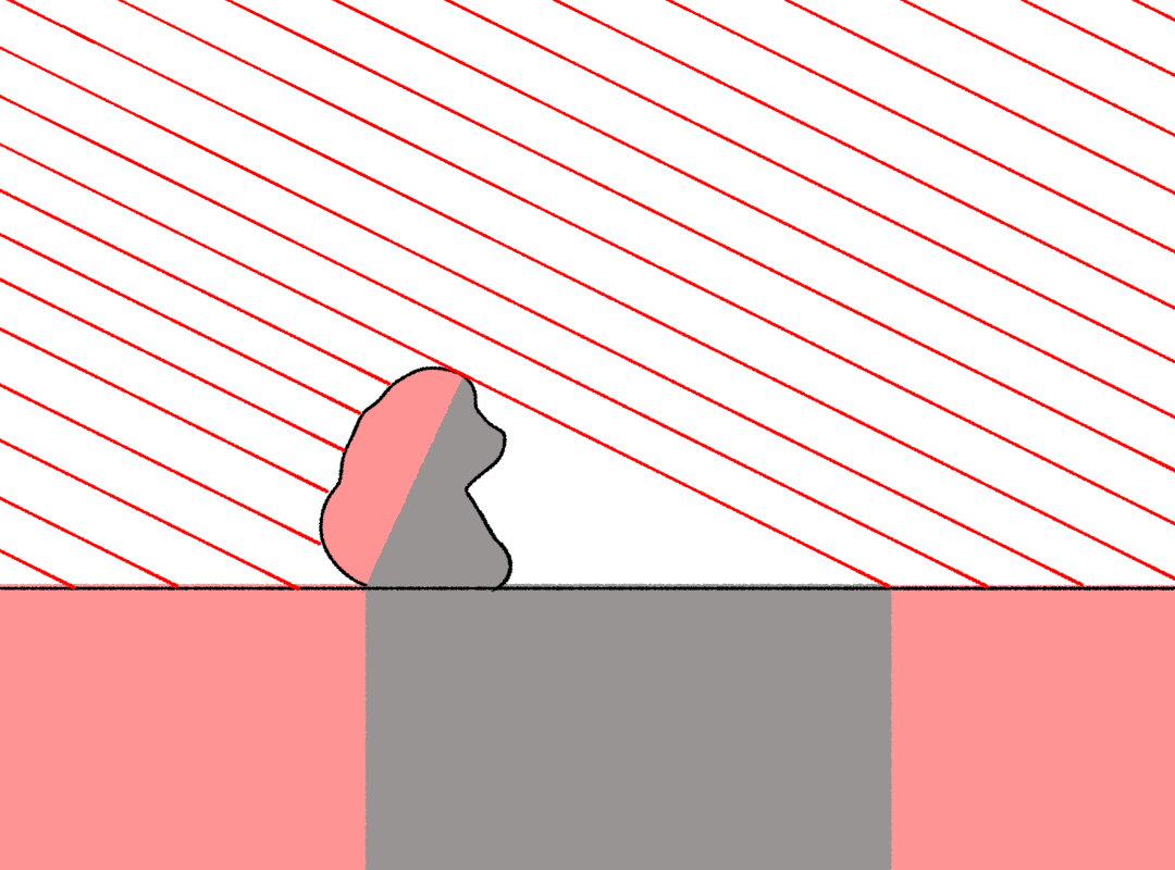
How can we construct this in 3D? We can intersect lines with lines, but intersecting lines with planes is harder. What we need is a line that is:
- in the same plane as the light ray, so its intersection with the ray is meaningful (represents a real point in 3D space and not just a coincidence)
- also in the ground plane, since that is where we’re drawing the shadow I will call this line the ‘baseline’ for the shadow. I have no idea if that’s standard terminology but I need a name, you know?
So we need to imagine a ‘shadow plane’ containing both the light ray and this ‘baseline’ that runs along the ground plane. However, this in itself gives us infinitely many possible choices of plane and baseline. How can we pin it down further? Let’s specify that the shadow plane contains the ground plane’s normal - a line that points directly away from the ground plane. This is generally a good choice because it’s often possible to construct the plane’s normal.
Knowing the normal, we can find a vanishing point for the baseline by drawing a line in the normal direction, connecting the ground plane’s vanishing line to the light source’s vanishing point. Sound kinda abstract? Let’s do some examples.
Shadows on a big flat plane
The simplest case, a flat ground plane and a level camera, is easy. The normal lines are all vertical, so you can drop a line straight down from the light source, and where it hits the horizon line, you have the vanishing point of the baseline.
Now all we need to do is draw a ray from the sun that goes through the top of the figure (more precisely, through the shadow terminator), and the baseline through their feet (the point on the ground plane directly underneath that point on the terminator).
With this information, we can draw in shadows at the right size. (If we wanted to be really precise, we could project every single point, but you really just need a few to anchor your drawing intuition!.)
Turn off the construction lines and throw in a few more values and you get something like this.
Shadows of slanting and floating objects
We can apply the same method to cast shadows of objects that are not upright, or even floating above the ground. The tricky part is that we need to know about a point on the plane directly underneath the point whose shadow we’re trying to project.
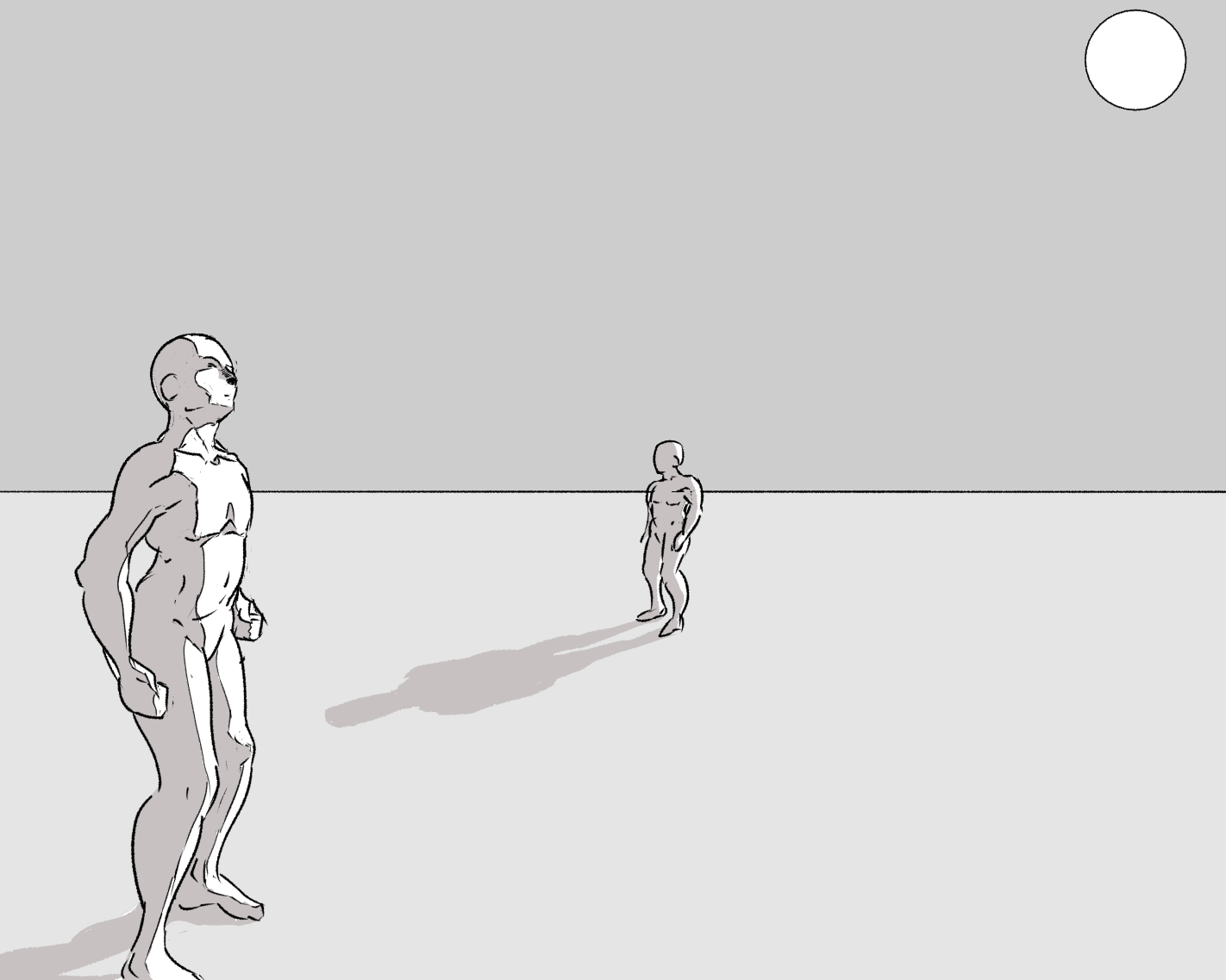
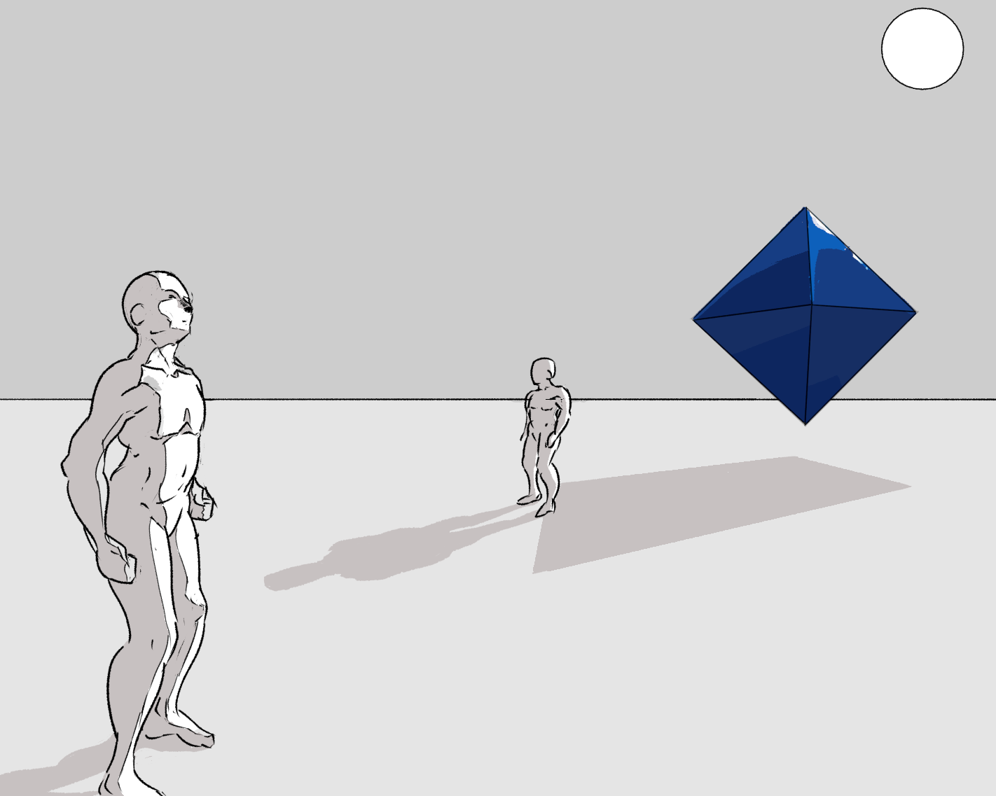
Let’s say our two figures on a plane are visited by an octahedron. (Any resemblance to angels living or dead are purely coincidental.) We know two of its vanishing points on the horizon line.
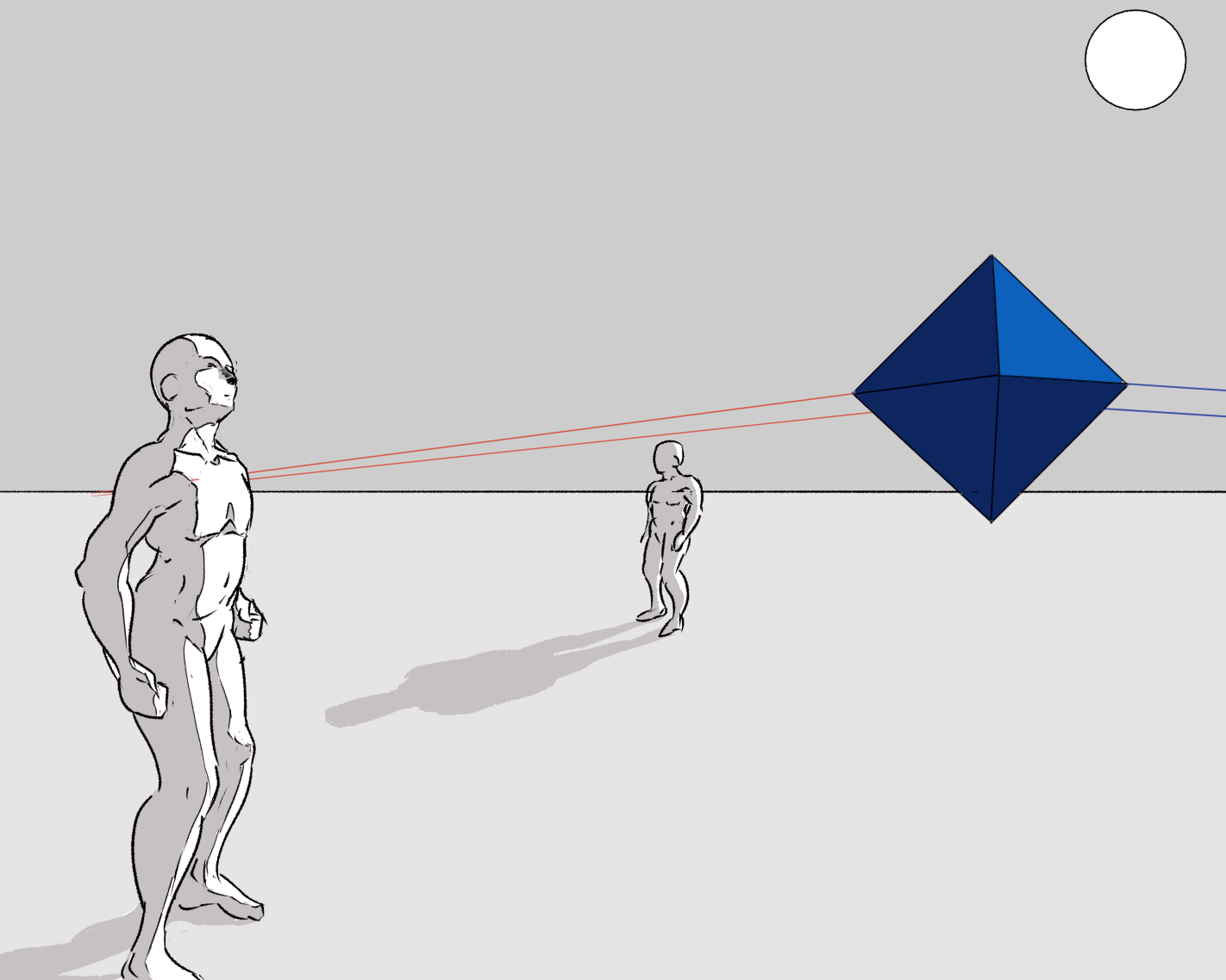
We can find the points directly underneath the corners of the octahedron by drawing a vertical line down from each one (since the camera is level, all the normal lines of the ground plane are parallel), and intersecting them with lines from these vanishing points. But first we need to make some decisions, like, is it small and near or large and far away? In practice, for this particular shape, we need to place one single point underneath, and from that we can construct the rest using vanishing lines. Like so:
Having found these points, we can then project the points of the octrahedron using the same method as the figures. The result is a kind of “sun’s eye view” of the octahedron projected onto the ground plane.
Now all we need to do is fill in the shadow we’ve created…
You can see that this technique can be used for just about any 3D shape, but of course the more points you project, the more effort it will take! It’s worth remembering at this point that it may be better to draw something inaccurate that still ‘looks right’ to you; it is unlikely that anyone will put this much scrutiny into whether your shadows are perfectly perspective accurate! Use this kind of exercise to build intuition, and handle unusual situations.
Shadows on a sloping surface
However, things get a big trickier if, for example, you’re trying to cast a shadow on an inclined plane in general. Not overwhelmingly so, but it requires some thought!
For now, I’ll just talk about how to do it if you already know the vanishing point of a plane’s normal. Next time, I’ll go into how we can find this vanishing point easily using the 90-degree circle.
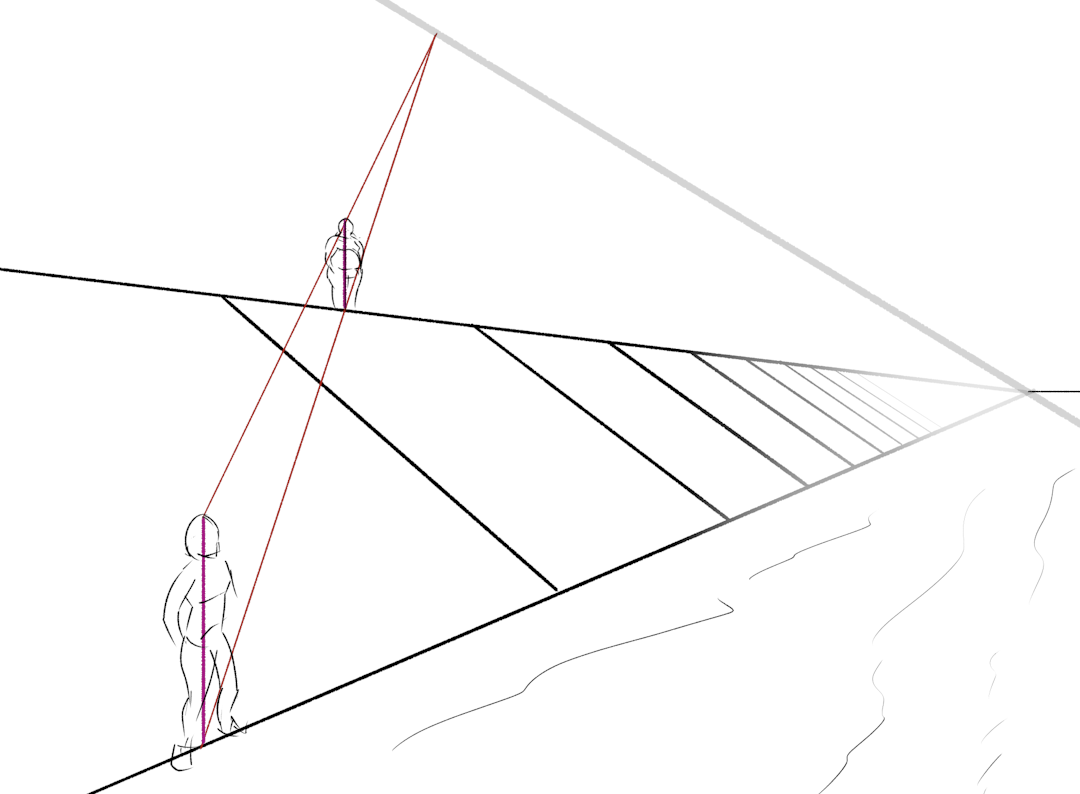
So, let’s say you’ve got a river bank. As an inclined plane, it has a tilted vanishing line. This time I rigorously constructed both the vanishing point of the normal, and the second vanishing point of lines going directly down the slope. We’ll go into that next time!
Anyway, using the methods discussed above, I spaced out regular slabs and placed a couple of figures. The camera is slightly lower than the river bank, so the horizon line of level ground is not visible in most of the picture. Here’s our riverbank:
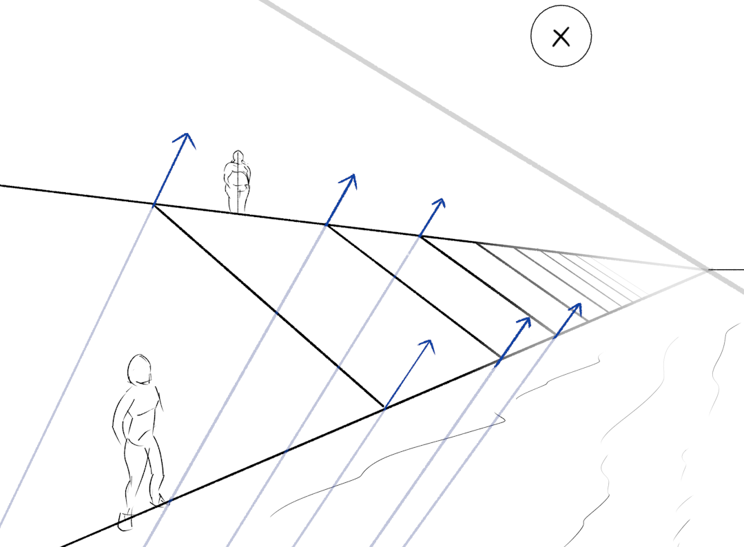
Now, we want these figures to cast shadows. So let’s put the sun somewhere in our picture—and make sure it’s above the plane’s vanishing line so the plane is not fully in shadow! (When the sun is close to this vanishing line, you’ll get long, dramatic shadows. When it’s far away—outside the picture area, generally—you’ll get smaller shadows.) We also need to know the direction of the plane’s normal. If you go to the effort of constructing it, the vanishing point of the normal is a long way outside the picture frame, but I drew some example normals so you get an idea where it is.
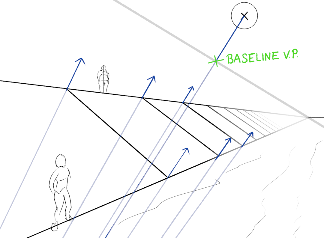
So, we first need to connect the vanishing line of our riverbank to the sun, in the normal direction. This gives us the vanishing point of shadow ‘baselines’. This is always going to meet the vanishing line at a right angle.
But, we can’t just draw a line through the head and feet like last time, because the figures are not standing normal to the riverbank! (These inclined planes really are a pain huh.) We need to do a bit of extra work: first extend a line in the river bank plane through the base of the figure, then connect it to the head of the figure with a normal line. Finally we can draw in the shadow baseline, and extend a shadow ray to meet it. Here’s an animation:
We’ve constructed the location of the head’s shadow; but to get a sense of how the proportions break down, we can construct other landmarks, like the neck and waist. This can be done in exactly the same way. Here’s an animation of how this construction traces out the line of the shadow:
The second figure in this picture is standing at the bottom of the bank, so basically none of their shadow will touch the bank. The water is level, so instead of the vanishing line of the bank, we just use the horizon line.
What about shadows that cut across plane changes? Let’s put a large bridge in the background of this picture. We need to portray two shadows: the one cast on the bank, and the one cast on the river. If our perspective constructions are accurate, these will line up nicely.
First, we should construct the shadow down the riverbank:
To do this, I imagined extending the plane of the riverbank a bit further until it met the bridge, which gave me one point on the edge of the shadow. Then I extended out a line from the sun through a fairly arbitrary point on the bridge—it doesn’t matter which one exactly, but I wanted one whose shadow point would be inside the plane of the picture. I found the corresponding point along the normal direction, and drew the baseline through it.
We can do something very similar for the water - we just need two points in the ground plane to connect with a line, and it really doesn’t matter if they’re visible or not.
As we’d hope, the shadows join up nicely. You might also notice that the shadow of the road is parallel to the road itself. In general, if you project the shadow of a line onto a parallel surface, the shadow line will be parallel to the original line. This is useful for example for quickly eyeballing a character’s shadow on a wall.
Shadows from behind the camera
If the light source is behind the camera, this creates an additional wrinkle. No matter how far you expand your picture, you’ll never draw the light source. But never fear! There is still a vanishing point: instead of being where the light is coming from, it’s where the light is travelling to.
In practice, this means you use largely the same constructions as we’ve just covered, but the vanishing point will typically be underground. For example, suppose we have a girl running in the desert.
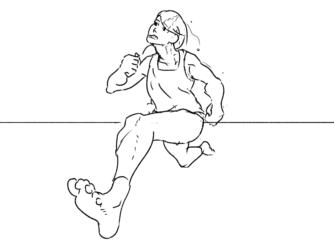
Let’s cast her shadow from behind the camera this time! The shadow vanishing point should be somewhere below the horizon line. We can connect that up to a baseline vanishing point. We also need to make sure we know the ground plane location of each point we intend to project, constructing out from one starting point.
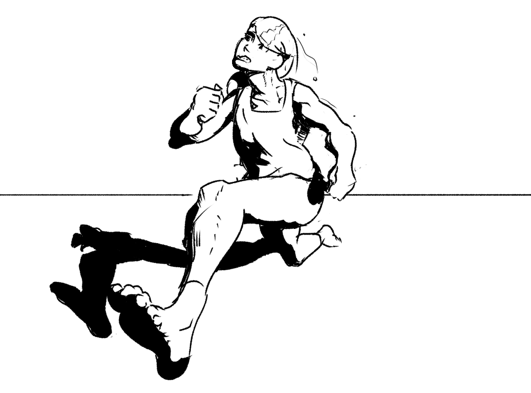
Now we can project shadows! The only difference is that the shadow ray crosses the baseline on the other side than we’re used to.
This one honestly came out kind of janky, probably a result of projecting too complex a shape. I tried adjusting the final shadow shape by eye in the last step, but even so, it looks odd to me. Nevertheless, let’s add some form shadows.
Bringing it all together
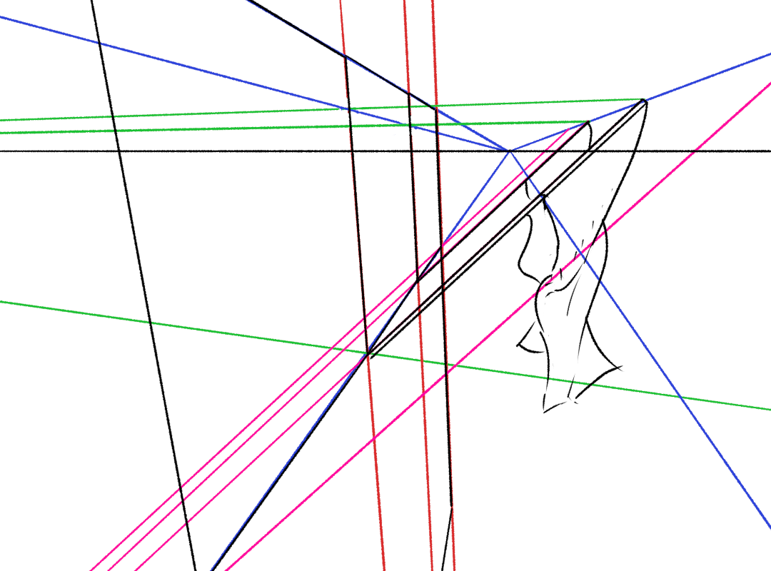
Suppose we have a building that has a line of diagonal flagpoles. We want the flagpoles to be evenly spaced, and all the same length and pointing in the same direction. So in short, we want to clone the length and direction of the flagpole along the front of the building. And for an extra twist, let’s put it in three point perspective. Perhaps a character is climbing into an embassy, and we want the camera angled down to emphasise the height.
So, let’s block out a three point perspective box (for now, just eyeballing the vanishing points) and drop in the first flagpole:
To copy the flagpole, we need two points: its start point and its endpoint. We have a line (the blue vanishing line) representing the starting points. The endpoints are being transported in the same direction as the start point, so we can connect the endpoint of the first flag to the blue vanishing point.
To space the starting points, we can use the method from the previous section. But what about the end points? To extend the starting points to the endpoints, we would need the vanishing point of the flagpole itself.
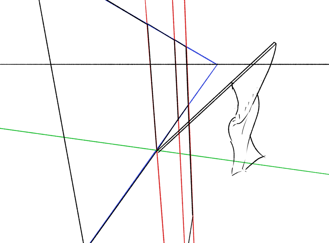
How you find this vanishing point will depend a bit on the particulars of the scene. In this scene, I figured I should use the green line that is perpendicular to the facade of the building to construct a second flagpole. Here’s the method:
If you can get two flagpoles down by some means, you can find their vanishing point by extending the lines until they cross. In this case they’re almost parallel in canvas space, so the vanishing point will be miles away outside the canvas. (Not a problem in digital, but if you’re drawing this on paper, probably just draw em parallel!) With this VP, we can connect the starting points to the ending points of the flagpoles.
Then, you know, draw the rest of the owl.

But what about shadows? We want our scene to have some values and shadow shapes to bring out the sense of “3D form” even further, right? (“Maybe you do.”)
The front of the embassy is vertical, and its vanishing point is also pretty much vertical. I’m going to put the light source (red vanishing lines) outside the picture frame (thank the art gods for Krita’s vanishing point tool) and work pretty briskly.
I hope this process is now comprehensible as something you could potentially use to cast a shadow now and again! Here’s the final embassy drawing…
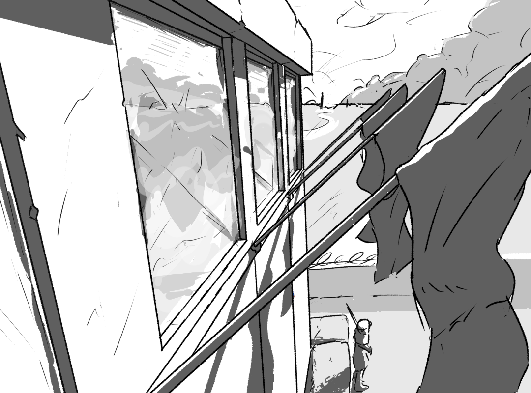
Those window reflections are pretty messy, aren’t they? Maybe next time we can look into reflective surfaces…
The next step
So far all of these tricks only handle translating lines, and synthesising new lines between known points. If we really want to be able to constract any object we want, we also really need to be able to rotate lines in 3D.
To do this, we need the power of the 90-degree circle. Which is the subject of the next article. Hopefully appearing in less than a year!
Comments
Krystal
Been checking every year to see if this was updated. Just leaving a comment in case it helps with motivation for the next article…Please continue when you can. Nobody explains this stuff as well as you do! :)
Sunchago
Thanks a lot for this entire profound explanation. I was struggling with the perspective of shadows in a particular scene, and this website was the only one that solved all of my questions. I bookmarked this page to learn more! With big thanks from Japan (^_^)
Will
Tour de force! Great job!