Hello again, welcome back to the THRUST//DOLL devlog. We’ve battled through the thicket of ‘generic jobs’, and now at last we should reach the clear plains of actually applying our hard-won knowledge to implement some gameplay…
Playing around with the movement controller we developed last time, there are a few obvious problems:
- if you thrust backwards in the direction you came from, your impulse cancels out your previous momentum and leaves you almost stationary. this feels awkward and unintuitive.
- you can gain arbitrary speed in discrete chunks, but it is hard to change direction and almost impossible to come to a complete stop. this is somewhat by design, and it will feel better once we have the option of using the grapple. however, we want the actual ‘thrust’, which is a limited resource, to feel ‘special’.
- the doll does not line up with the direction you are moving.
- there is no UI indication of when you are able to thrust.
- thrusting feels exactly the same as coasting, instead of an intense, powerful force.
- the camera system is not yet full 6DOF, as we can’t roll the doll. this makes it hard to target straight up and straight down.
Some of these problems will be easier to address than others. For example, animations and effects will be important to ‘sell’ the thrust, and that will require some work to author. We’ll hold off on that for now. However, the basic motion can also have a better feeling.
So in order let’s implement…
- interface element to show whether we’re thrusting
- rotating the doll to face the direction of travel
- friction/acceleration model
- roll input
But first, some housekeeping!
Custom ComponentSystemGroups
We’re starting to build up a lot of systems now, and creating special logic to decide when each of them should run is a bit of a pain. (The way I’ve been doing it is by creating special singleton components like Configurator and Level which bring the relevant systems online.)
For this reason I thought I’d go ahead and create some custom system groups. These are essentially just systems which contain a list of systems to update. Here’s the two I made:
using Unity.Entities;
using Unity.Transforms;

[UpdateBefore(typeof(TransformSystemGroup))]
public class ConfiguratorSystemGroup : ComponentSystemGroup
{
    protected override void OnCreate()
    {
        RequireForUpdate<Configurator>();
        base.OnCreate();
    }
}

[UpdateBefore(typeof(TransformSystemGroup))]
public class LevelSystemGroup : ComponentSystemGroup
{
    protected override void OnCreate()
    {
        RequireForUpdate<Level>();
        base.OnCreate();
    }
}
Here Level is a new component which will contain some config data for the level—mouse sensitivity, effect durations and cooldowns, etc. We can look it up with GetSingleton.
The general sentiment is that you shouldn’t turn systems on and off too often, but here these systems are very strongly tied to particular scenes, so it seems to me that they should be turned off as a unit.
The frame drops when moving the mouse
There is a small but noticeable increase in the frame time when we move the mouse and rotate the camera. Interestingly, this slowdown persists even when I turn off the systems relating to camera rotation, so it doesn’t seem to be that my code is somehow slow.
However, the editor loop is going to confuse things. To profile properly we need to make a build.
There was a small issue with Latios not building correctly. A few files needed tweaks to build properly outside the editor—these have now been fixed, so download Latios 0.6.5 and you should be good to go. That done, we can do a bit of profiling.
…or so I thought. Unfortunately, I ran into a Unity bug that meant my builds weren’t looking in the right place for a linked library that was essential for Latios. The result was that the build would segfault as soon as it tried to call a function from within that library. So, profiling is for now not possible.
I filed a bug report with Unity so hopefully it will get fixed before too long.
Creating a UI element to represent a targeting reticule
It’s time to create another ‘vector graphics in a fragment shader’ UI element. Maybe I should make a library for this lmao.
We’ve already learned to draw circles, but I would like to be able to draw a circular arc to represent the amount of cooldown remaining on the thrust. This can be computed with an atan2 call, which returns an angle between \(-\pi\) and \(\pi\).
I don’t think I’ve talked about this yet in these devlogs beyond the high-level overview in devlog 1. So let’s talk now about how we went about creating one of these UI elements.
A proper explanation of a billboard shader
The basic UI element is a a quad with a billboard shader. The billboard shader means that no matter how the camera moves, the quad will appear face-on to the camera. When researching this, I found many different implementations of billboard shaders, but most of them were overcomplicated or incorrect when I tried to copy them. To reach a real understanding we must crunch the maths ourselves.
A detailed explanation of billboard shader maths
A rasteriser applies a series of matrix transformations to project points from their starting ‘model space’ into their eventual position in perspective-projected ‘clip space’.
- Points start off defined relative to the model origin.
- First we multiply by the model matrix, which takes us from object (or local) space to world space—where the model is placed, which way it’s facing, and whether it’s been made bigger or smaller. This matrix is sometimes called the local to world matrix; in DOTS it’s stored on the
LocalToWorldcomponent. - Next, we multiply by the view matrix, which takes us from world space to camera space. Essentially this applies the location and orientation of the camera, by moving and rotating everything else relative to the camera position. This is the inverse of the camera’s
LocalToWorldmatrix. - Finally, we multiply by the perspective matrix. This projects all the points in Euclidean 3D space into the weird projective geometry world of Clip Space, and then the homogenous coordinates are normalised to get Normalised Device Coordinates. The triangles can now be frustum culled and rasterised into fragments, the fragments can be depth culled, etc. before passing to the fragment shader.
The last part’s beyond the scope of this devlog, but if you’re interested, I recommend Scratchapixel. You can also read about my own attempts to implement a rasteriser in C++ back in 2017.
These matrix transformations are the job of the vertex shader. By default, the vertex shader simply multiplies every vertex by a combined MVP matrix, but if there’s any code you want to run per vertex, or values you want to be interpolated over triangles, you can write a custom vertex shader.
A billboard shader thus wants to avoid applying the rotation component of the view matrix, in order that the rotation of the billboard is exactly the same as the camera. What do I mean by ‘rotation component’? Well, given an affine transformation matrix, we can break it down into the product of a translation, rotation and scale (and shear maybe, but not in this case). So if our model \(\mathbf{M}\)-view \(\mathbf{V}\)-projection \(\mathbf{P}\) transformation is \(\mathbf{PVM}\), and we decompose the view and model matrices into a translation \(\mathbf{T}_i\), rotation \(\mathbf{R}_i\) and stretch \(\mathbf{S}_i\), the model-view projection matrix becomes
\[\mathbf{P}\mathbf{T}_\mathrm{V}\mathbf{R}_\mathrm{V}\mathbf{S}_\mathrm{V}\mathbf{T}_\mathrm{M}\mathbf{R}_\mathrm{M}\mathbf{S}_\mathrm{M}\]So we want to knock out \(\mathbf{R}_\mathrm{V}\).
Unity’s Shader Graph—which we have to use for the sake of compatibility with DOTS—adds an extra complication. The Shader Graph vertex shader requires you to give it coordinates in object space, and tacks on the MVP transform at the end when it generates the actual shader code for you.
In Shader Graph, Unity can give us the inverse of the view matrix \(\mathbf{V}^{-1}=\mathbf{S}_\mathrm{V}^{-1}\mathbf{T}_\mathrm{V}^{-1}\mathbf{R}_\mathrm{V}^{-1}\). So if we multiply our vertices by this in shader graph, we get (ahem)
\[\mathbf{P}\mathbf{T}_\mathrm{V}\mathbf{R}_\mathrm{V}\mathbf{S}_\mathrm{V}\mathbf{T}_\mathrm{M}\mathbf{R}_\mathrm{M}\mathbf{S}_\mathrm{M}\mathbf{S}_\mathrm{V}^{-1}\mathbf{T}_\mathrm{V}^{-1}\mathbf{R}_\mathrm{V}^{-1}\]So we need to commute matrices around to get them to cancel out. However, we don’t want to knock out the translation part of the camera matrix. We can avoid applying this by setting the \(w\) coordinate to zero before multiplying by the inverse vew matrix. So that effectively sets \(\mathbf{T}_\mathrm{V}^{-1}\) to identity in our product.
\[\mathbf{P}\mathbf{T}_\mathrm{V}\mathbf{R}_\mathrm{V}\mathbf{S}_\mathrm{V}\mathbf{T}_\mathrm{M}\mathbf{R}_\mathrm{M}\mathbf{S}_\mathrm{M}\mathbf{S}_\mathrm{V}^{-1}\mathbf{R}_\mathrm{V}^{-1}\]Now we need to get across the model matrix. We don’t completely want to get rid of the model matrix, since it’s good to be able to scale interface elements up and down, and we need to position them in the world. But we can at least set the model rotation to identity (by not rotating the model).
\[\mathbf{P}\mathbf{T}_\mathrm{V}\mathbf{R}_\mathrm{V}\mathbf{S}_\mathrm{V}\mathbf{T}_\mathrm{M}\mathbf{S}_\mathrm{M}\mathbf{S}_\mathrm{V}^{-1}\mathbf{R}_\mathrm{V}^{-1}\]The camera is never scaled so we can delete \(\mathbf{S}_\mathrm{V}\) and its inverse.
\[\mathbf{P}\mathbf{T}_\mathrm{V}\mathbf{R}_\mathrm{V}\mathbf{T}_\mathrm{M}\mathbf{S}_\mathrm{M}\mathbf{R}_\mathrm{V}^{-1}\]In fact, this matrix product is actually exactly what we want. If the model is translated in space, we want this translation vector to be rotated if the camera is rotated. But this will make sure the model is aligned with the camera, wherever it ends up.
Here’s the resulting shader, which is actually super simple:
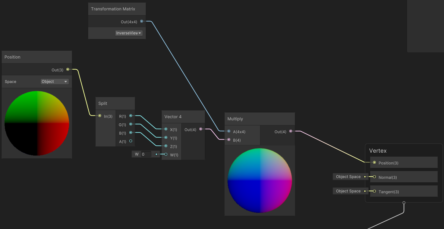
This shader works great as long as the quad’s rotation is set to identity. If it’s not… weird things happen.
We could also achieve a similar effect on the CPU by copying the camera’s rotation to the billboard element. In fact, given I plan to parent the billboard element to the camera pivot anyway, we shouldn’t use the billboard shader in this case! Still, it’s a gadget we have on hand.
Drawing circles with a fragment shader
Having oriented a quad to always face the camera, what do we do with it? I essentially use it as a canvas for vector graphics.
The quad has UV coordinates, which range from \((0,0)\) in the bottom left corner to \((1, 1)\) in the top right corner. These are automatically interpolated by the GPU. You can do lots of clever things with UV coordinates, but in this instance, they simply give us a 2D Cartesian space.
We want to draw circles, so we need to convert this Cartesian space into a polar coordinate system centred on the centre of the quad.
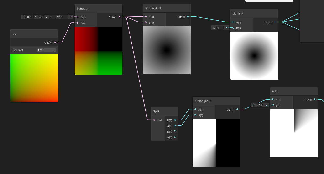
For some reason, Unity gives us the UVs in a float4 homogeneous coordinate, i. e. \((u, v, 0, 1)\). By subtracting this from \((0.5,0.5,0,1)\) we get into a Cartesian coordinate system with \((0.5,0.5,0,0)\) in the bottom left ranging from \((-0.5,-0.5,0,0)\) in the top right.
To get the radial coordinate—we don’t need the absolute distance really, just its square, which saves us having to calculate a square root. So we just dot this with itself. Now we have a value that increases from 0 in the middle of the quad out to 0.25 at the inscribed circle. It is more convenient if it just reaches 1 at the edges, so we multiply it by 4. Now if we test whether this value is less than 1, we get a circle that fills the quad.
That’s enough if you want to draw a solid circle, but I want to have a circular progress bar that gradually fills up as the cooldown ticks down. This means we also need the angular coordinate.
To calculate the angular coordinate from two cartesian coordinates you use the arctan2 function. This gives us a value ranging clockwise from \(-\pi\) around to \(\pi\). I then add \(pi\) to this to get a value that ranges from \(0\) to \(2\pi\). Arctan2 is an expensive function to call in a fragment shader, but the number of fragments here is so small that I doubt we’ll notice.
With these elements in hand, we can draw a circle. This is mostly done by composing comparison functions with multiplication and addition. Here’s the next part of the shader:
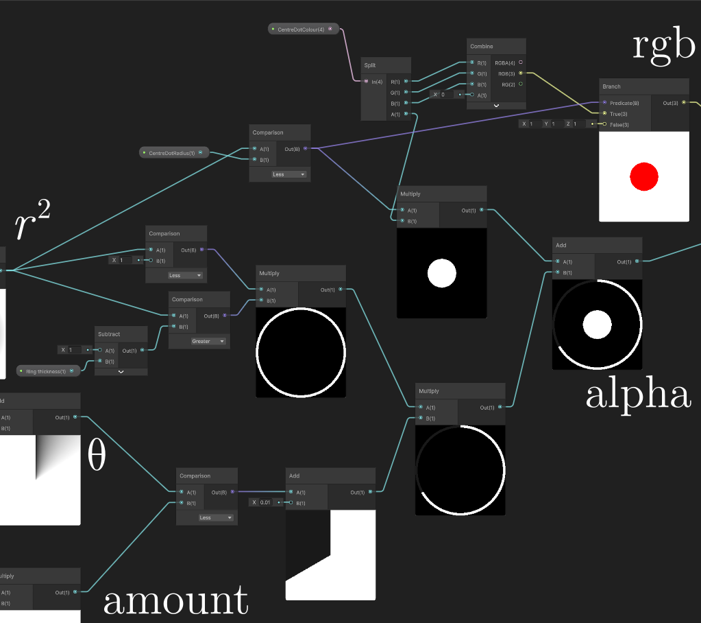
There’s two main paths in this shader.
The bottom half is for drawing the progress bar. We feed the shader an amount field using a hybrid per instance override, and threshold the polar coordinate. We draw a circle by multiplying \(r^2 < 1\) and \(r^2 > (1-\text{ring thickness})\).
The top half is for drawing the dot in the middle. We give it a radius and a colour. The colour is split into an RGB component and an alpha. We apply both when the radial coordinate is smaller than the radius. Since there’s no overlap between the figures we’re drawing, we can just add the alpha values together. We can change the colour of the dot in the middle to communicate state.
Here’s how it looks in-game:
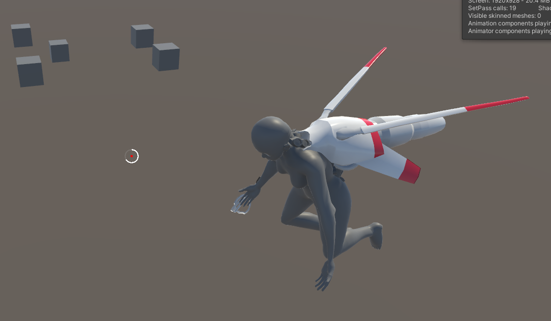
We haven’t connected this to game logic yet, but there are a few issues. Right now this is quite jaggy and aliased. We can address this by using smoothstep instead of direct comparisons. However, I’ll worry about that later. Secondly, it is hard to see against a white background. This may not be an issue depending what sort of environments we put our doll into.
Animating this progress bar
The shader’s at least done enough to develop further, now we need to hook it up to systems. This is actually super easy. First we gotta set components to override material properties…
using Unity.Entities;
using Unity.Rendering;
using Unity.Mathematics;

[MaterialProperty("_Amount")]
partial struct ReticuleCooldownRing : IComponentData
{
    public float Amount;
}

[MaterialProperty("_CentreDotColour")]
partial struct ReticuleColour : IComponentData
{
    public float4 Colour;
}
Then a system to update them. Putting everything in a job means that it can be automatically scheduled after the previous job that updates the transform cooldown.
using Unity.Entities;
using Unity.Burst;
using Unity.Mathematics;

[BurstCompile]
[UpdateInGroup(typeof(LevelSystemGroup))]
[UpdateAfter(typeof(StatusTickSystem))]
partial struct ReticuleSystem : ISystem
{
    [BurstCompile]
    public void OnCreate(ref SystemState state)
    {

    }

    [BurstCompile]
    public void OnDestroy(ref SystemState state)
    {

    }

    [BurstCompile]
    public void OnUpdate(ref SystemState state)
    {
        ComponentLookup<ThrustCooldown> thrustCooldownLookup =
            SystemAPI
                .GetComponentLookup<ThrustCooldown>();

        Entity playerEntity =
            SystemAPI
                .GetSingletonEntity<Character>();

        new ReticuleJob
            { ThrustCooldownLookup = thrustCooldownLookup
            , PlayerEntity = playerEntity
            }.Schedule();
    }
}

partial struct ReticuleJob : IJobEntity
{
    public ComponentLookup<ThrustCooldown> ThrustCooldownLookup;
    public Entity PlayerEntity;

    void Execute(ref ReticuleCooldownRing cooldownRing, ref ReticuleColour dotColour)
    {
        if ( ThrustCooldownLookup.TryGetComponent(PlayerEntity, out ThrustCooldown cooldown))
        {
            cooldownRing.Amount = cooldown.TimeRemaining * cooldown.InverseDuration;
            dotColour.Colour = new float4(1f, 0f, 0f, 0.5f);
        } else {
            cooldownRing.Amount = 0f;
            dotColour.Colour = new float4(1f);
        }
    }
}
With feedback, you’re a lot less likely to futilely click and hope for a thrust. But there’s still not much evidence for when you’re thrusting and when you’re not.
Adding damping
Although this is a game of high speed movement, for movement to be meaningful you need to have some constraint to push against.
The main constraint we have is that it’s tricky to control direction, so you have to cleverly apply your limited thrusts, and appropriate grappling hooks, to steer through the level. However, if we want the ‘thrust’ state to feel meaningfully forceful, it makes sense to add a small amount of resistance, which will in effect impose a maximum speed when thrusting and cause speed to gradually decay when not.
We could even apply a weak thrust when we’re not doing the actual thrust ‘action’, so there’s effectively both a minimum and a maximum speed.
Damping is fairly easy to include in our equations of motion. Real air resistance is proportional to the square of velocity, and this seems like a reasonable place start.
using Unity.Entities;
using Unity.Burst;
using Unity.Mathematics;

[BurstCompile]
[UpdateInGroup(typeof(LevelSystemGroup))]
[UpdateAfter(typeof(ThrustAccelerationSystem))]
[UpdateBefore(typeof(VelocitySystem))]
partial struct DragSystem : ISystem
{
    [BurstCompile]
    public void OnCreate(ref SystemState state)
    {

    }

    [BurstCompile]
    public void OnDestroy(ref SystemState state)
    {

    }

    [BurstCompile]
    public void OnUpdate(ref SystemState state)
    {
        float deltaTime =
            SystemAPI
                .Time
                .DeltaTime;

        new DampingJob
            { DeltaTime = deltaTime
            }
            .ScheduleParallel();
    }
}

partial struct DampingJob : IJobEntity
{
    public float DeltaTime;

    void Execute(ref Velocity velocity, in Drag drag)
    {
        velocity.Value -=
            drag.Coefficient * velocity.Value * math.length(velocity.Value);
    }
}
The drag coefficient is a new component that is currently only applied to the player, but in the future this system can be used to put drag on just about anything.
Rotating the doll to align to the direction of motion
So this one’s a little tricky.
Suppose the doll is travelling in a direction \(\mathbf{v}_1\), and it receives a thrust that leaves it travelling in a direction \(\mathbf{v}_2\). The doll also has what we could call an ‘up’ vector coming out of her back; we could also call this a ‘dorsal’ vector; let’s call it \(\mathbf{u}\). If you know both these vectors, you know which way she’s pointing precisely.
The problem we have is that the operation ‘rotate to align \(\mathbf{v}_1\) with \(\mathbf{v}_2\)’ is unconstrained. Depending on your choice of rotation, you could have \(\mathbf{u}\) end up in a whole ring of positions. There is a ‘natural’ approach, which gives the smallest possible rotation; this is to rotate around the cross product \(\mathbf{v}_1\times\mathbf{v}_2\). However, this may not always be what we want, since we also need to think about the camera and its Euler angles.
Angular damped spring
Still, let’s go about implementing this, and consider whether we want to implement a different strategy later. We can use another one of our cooldown jobs to handle the rotation. Ideally we want a little bit of anticipation, easing, overshoot and settle to make it feel dynamic. This could potentially be handled with a state spring like the ones we used in the configurator. But better yet, we could create a dynamic rotation system which attempts to orient the doll towards a target but also tracks angular velocity.
Let’s think about how to do this. In Newtonian mechanics, we don’t think about quaternions, but we think of the angular velocity \(\mathbf{\omega}\) as a vector perpendicular to the direction of rotation. Then we apply torques to it according to the equation
\[I\dot{\mathbf{\omega}}=\mathbf{\tau}\]where \(\mathbf{\tau}\) is the torque, and \(I\) is the moment of inertia (in general a tensor, but we can treat it as homogeneous here).
Given the angular momentum vector, we can turn it into a quaternion representing the differential rotation using the AxisAngle method. The torques we will apply will be based on the angle between the current forwards direction and the target, and then a damping factor.
So, here’s an implementation of that algorithm. It has some problems, as we’ll see.
First of all, here are the new components we will add.
using Unity.Entities;
using Unity.Mathematics;

partial struct AngularVelocity : IComponentData
{
    public float3 Value;
}

partial struct RotationTarget : IComponentData
{
    public float3 Target;
}

partial struct DampedRotationSpring : IComponentData
{
    public float Stiffness;
    public float Damping;
}
Nothing complicated here. We have the direction we want to go, the current angular velocity, and spring parameters. These are added to CharacterAuthoring/CharacterBaker, exposing the stiffness and damping in the editor, and anything else we want to use this mechanic in future.
Now, systems. First, the AngularVelocitySystem actually applies the rotation deltas from the angular velocity. (Don’t use this as-is, it has a problem I’ll get to shortly.)
using Unity.Entities;
using Unity.Burst;
using Unity.Transforms;
using Unity.Mathematics;

[BurstCompile]
[UpdateInGroup(typeof(LevelSystemGroup))]
partial struct AngularVelocitySystem : ISystem
{
    // usual stuff, create the job, pass the delta time and schedule it
}

partial struct AngularVelocityJob : IJobEntity
{
    public float DeltaTime;

    void Execute(ref Rotation rotation, in AngularVelocity angularVelocity)
    {
        float angle =
            math.length(angularVelocity.Value) * DeltaTime;

        quaternion deltaRotation =
            quaternion
                .AxisAngle
                    ( angularVelocity.Value
                    , angle
                    );

        rotation.Value =
            math
                .mul
                    ( deltaRotation
                    , rotation.Value
                    );
    }
}
We generate a quaternion to represent the delta rotation and then premultiply it with the current rotation. This means we will never gimbal lock.
Now, to actually generate that angular velocity:
[BurstCompile]
[UpdateInGroup(typeof(LevelSystemGroup))]
[UpdateBefore(typeof(AngularVelocitySystem))]
partial struct RotationSpringSystem : ISystem
{
    // usual stuff
}

partial struct RotationSpringJob : IJobEntity
{
    public float DeltaTime;

    void Execute
        ( ref AngularVelocity angularVelocity
        , in Rotation rotation
        , in DampedRotationSpring spring
        , in RotationTarget target
        )
    {
        float3 currentOrientation =
            math.mul
                ( rotation.Value
                , new float3 (0, 0, 1)
                );

        float3 torque =
            spring.Stiffness
                * math.cross
                    ( currentOrientation
                    , target.Target
                    );

        angularVelocity.Value +=
            ( torque - spring.Damping * angularVelocity.Value)
                * DeltaTime;
    }
}
Honestly not sure the best approach to splitting these lines. Is it more readable if it’s a one-liner? Anyway.
We get the current orientation of the character by rotation a unit vector in the z direction by the current rotation quaternion. Then we take the cross product with the orientation we want to get to. Finally we integrate. It’s almost exactly the same as the linear damped spring, but now we’re in three dimensions.
Except it’s not exactly the same. The cross product means we have a force proportional not to the angle between the destination and target, but the sine of that angle. Which means that if we want to spin to rotate backwards, we will start with a small force, but if we want to rotate by a right angle we will start with a large force. This feels very unnatural.
But enough talk, have at thee let’s show a video of all this in action…
As you can see, taking the shortest possible rotation path means the doll very quickly gets turned on its side, upside down, etc. The rotation also feels very rigid and stiff, although this is to be expected.
However, there’s an even weirder problem. If you fly around for a while in this system, the doll starts to get really skewed and distorted. Have a look at this…

Whoah she’s been skewed and squashed, what’s going on?
The answer is that we’re doing a quaternion multiplication every frame, which means floating point errors compound. A normalised quaternion—that is, a quaternion whose norm is 1—represents a rotation, but an unnormalised quaternion represents some other weird transformation. So if we normalise our quaternions we should prevent this problem. We could do this every frame…
rotation.Value =
    math.normalize
        ( math.mul
            ( deltaRotation
            , rotation.Value
            )
        );
Annoyingly, you have to read this ‘inside out’: first the rotation is applied then the normalize. This is where a function composition (‘pipe’) operator would be really handy. Ugh, programming in a functional language really leaves a mark on a girl.
Quaternion normalisation is a fairly expensive operation, on top of the quaternion multiplication we’re already doing. If we end up with a lot of objects with angular momentum in the future, we could consider trying to spread this out across multiple frames if the profiler shows it to be a problem.
Having solved the big bug, now we have to make this not suck.
Better rotation
There are two big problems with the model as it stands.
- the cross product sine problem: as discussed above, the easing between intended and target position depends on the angle between starting and target vectors in an unintuitive way.
- the roll problem: relative to the camera, it is likely for the doll to be turned sideways or upside down after a few rotations. This means it would be wildly counterintuitive to use the doll’s ‘up’ vector for our camera’s ‘up’ vector.
Both of these suggest that we’re going about this in the wrong way. Let’s think about the problem a little harder.
We can broadly consider two types of rotations. There are rotations on a flat disc, where the doll can rotate without changing its ‘up’ vector. Then there are rotations that tilt up or down, which force the doll to tilt its ‘up’ vector forwards or backwards.
There is actually a quaternion constructor that takes into account an ‘up’ vector and a direction. However, the difficult part of this is finding the delta-rotations to animate smoothly towards this position.
The algorithm we may be looking for is the appetisingly named slerp, or spherical linear interpolation. This is another way of envisioning the axis-angle construction we used in the previous section. We can imagine the direction the character is pointing as following a path along the surface of the unit sphere. This path is a great circle, the geodesic of a sphere.
So, let’s consider how to do a slerp with easing. There is a slerp function in the Mathematics library, so we can simply animate the parameter to get a slerp between two orientations. Rather than a spring, in this case we may want to go for a consistent, fixed time, and give it some kind of (cubic?) easing function.
We’ll go into this in the next devlog.
Improving the doll model
There were a couple of issues with the doll model that needed dealing with.
Fixing forearm twisting
The arm deformation, which only had one arm for the forearm, led to very jank deformation when the hand is twisted…
This is due to the lack of splitting the forearm in two, a technique called a ‘roll bone’. The base rigify rig doesn’t have this problem, but the script I was using to convert it into a Unity-friendly rig actually combines the split forearm and upper arm bones into single bones. I actually think I don’t need this script after all, because I’m not using Unity’s humanoid animation system, so there is no need to force my bones to fit a particular pattern.
If I go back to the default Rigify rig, remove all the bendybones since they’re not supported by Unity, and do a little weight painting to compensate, we get much nicer deformation…
The forearm twists in a way that’s somewhat realistic, with the ulnar and radius twisting around each other. (Try rotating your hand and see!) It’s not perfect, there are some wrist positions that still look a little weird, but acceptable for this point and we can consider the twist issue solved.
Adding details to the rocket thruster
I didn’t feel like the thruster I’d designed quite had that ’90s mecha’ feel, so I modelled in a few extra details.
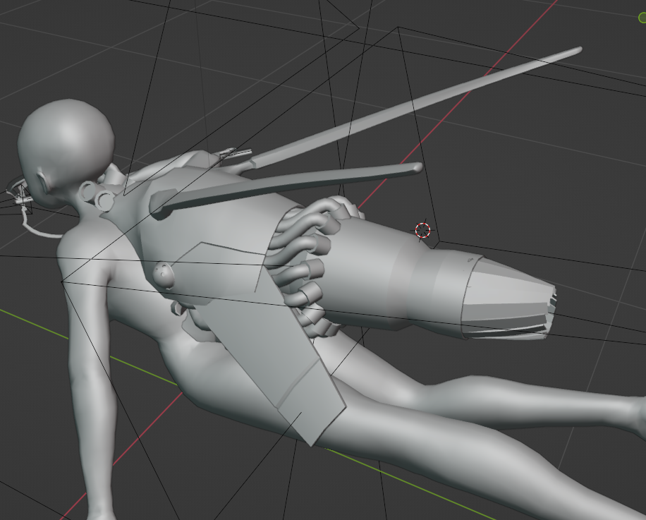
I cut the corner off the upper shell section, added a panel line, and added a small swivelling ball with three dots reminiscent of (for example) the spider tanks in Ghost in the Shell. I also replaced the lower section with a set of vanes that could be used to throttle thrust. And I added a ring of tubes coming out from under the upper shell to go into whatever the kind of… reaction chamber part of the engine is. I can definitely stand to add more details, but this is going pretty well.
Improving shoulder deformation
The modelling should give reasonable deformation around the shoulder by default, but for some reason the shoulder bone isn’t included in the IK chain in rigify, so we have to move it manually. There are provided handles for this. When you raise your arm above your head, your clavicle moves upwards and your shoulder blade swings out to the side. We also want to preserve the volume of the deltoid.
Getting good shoulder deformation is tricky, because there are a lot of bones that affect this area, and all of them have to blend in sensible ways. We have two spine bones which control the essentially rigid ribcage, left and right ‘shoulder’ bones that represent the shoulder girdle (scapula and clavicle), breast ‘bones’ that can be used to move the soft tissue of the breast (in a film this would be done by a simulation but we’re not in a film lol), and the upper arm bones. We need to blend between these in a way that’s natural.
Here’s what I came up with:
I don’t have much geometry on the side of the torso, so I can’t really give a convincing armpit shape (the indentation of which is created by the pectoral muscles at the front and various back muscles at the back) without adding more geometry there. If it’s a major issue I can go back and extrude in an extra loop there.
Hips again
Since we regenerated the rig, we need to redo the hip deformation, since the auto-weight painting leads to some issues where it doesn’t quite follow our deform lines. Here’s where I got to. It’s not perfect but it’s better.
With really tight angles, we see a bit of self-intersection in the model. This can’t really be helped at the level of precision we’re working with here. In reality, when you fold your arm or leg that tightly, the fat and muscles have to squish to make room. That’s not something I know how to simulate in Unity (and it sounds hilariously expensive computationally). Fortunately, it shouldn’t be an issue in the game.
Issues with the fingers
Rigify attempts to work out which way limbs bend based on the curvatures in the ‘metarig’. Mostly it works great, but some of the fingers are bending in weird ways. I expect it’s possible to fix manually, probably by finding the relevant control bones for the fingers and rotating them a bit, but it’s kinda fiddly so I have just worked around it so far.
So where are all those toggleable cyborg parts then?
That’s tomorrow’s job. Here’s a list of things we will need to model…
- adrenal hyperprocessor
- an assembly that attaches to the top and back of the doll’s head. We want more of a Tsutomo Nihei or Ghost in the Shell vibe than Frankenstein’s monster, but there should be some kind of uncomfortable needle going into the brain, like an electrocorticography, but also the regular patterns of something mass produced.
- helical tension rod
- a component that relates to the grappling hook. This could have no visible representation, but I’d like to come up with something. Theoretically, it would go inside the shoulder spool, so possibly we could consider adding components there?
- spacetime lacunae
- a wormhole generator that replaces the stomach. The actual component I wanted to involve a sphere somehow, but the question is how to make it flow nicely with the model around it. We could also consider other shapes. The main issue is that replacing the stomach is like to require modifying the geometry. We may need to make a few swappable variant models and toggle their visibility.
- digitgrade elastication
- this one’s an even bigger puzzle. I want to imply that the doll’s legs have been surgically replaced with cyborg ones. However, we could also consider an attachment that goes over the existing legs and extends the foot, which would allow preserving the original geometry. Long legs are very Nihei. Drawing some concepts will help find the answer.
- ablative mucosa
- attaches to the shoulder on the deltoid muscle. A shield generator—the shape language for this (circular discs) is well established in scifi. But we could consider some more organic shapes instead.
- thrust membrance
- the name of this one is an allusion to Charity’s short story collection Throst Membrances, but this leaves open the question of what a thrust membrance actually looks like. But it will be some kind of mechanical gubbin. Maybe some kind of vanes that resemble gills.
- attitude vanes
- this was originally planned to be some kind of large sail-like structure extending out the front and back of the doll, but actually I think we already have a component of the model that would suit. The wing-like structures coming out the bottom of the thruster could either be considered the attitude vanes themselves, or support expansion into attitude vanes.
- trypophilia
- some kind of extra wormhole effect added to the spacetime lacunae. This will depend on what design I settle on for the lacunae itself.
- gluteal hypertrophy
- the glutes are your ass muscles. the joke is this is a silly sciencey way of saying “makes your ass bigger”. this could be done with a shape key, but some kind of external cyber-muscles would probably make more sense.
all right so what’s next
We still have to iron out the exact mechanics of movement. At some point we’re going to need to implement some concept like a state machine to handle the various conditions the player might be in, and transitioning between them. For example, going from ‘coasting’ to ‘transitioning to thrust’ to ‘thrusting’, each with their implications for animation. Another state with animation implications is ‘attached to a wall’. I’d also like to have animations to show for example ‘receiving damage’. We can use tag components to represent states, or use a single component storing an enum.
This doesn’t have to be quite so complicated as a normal third person animation controller since we don’t have to handle walking, strafing etc. However, there is a different complication. Ideally I would like the character respond to the direction the mouse is pointing by looking, pointing her arm, etc. Additionally, we have some rather complicated rotation transitions to handle. All of this suggests that we want to take programatic control of bones. And it further suggests that what we want is… Inverse Kinematics.
IK is a planned feature for Kinemation in the future, but it’s not going to be there before the end of my course. That’s fine though because that’s an exciting opportunity to learn how to implement IK, and if it goes well, I could even feed my work back into the Latios Framework.
Some cursory research suggests that a good choice for IK algorithm would be FABRIK, an algorithm developed in 2011 which promises more natural results at less computational cost than the Jacobian-based methods used in most 3D packages. It also claims to be easy to add on top of authored animations, and there are papers on extending it to deal with constraints etc. (I learned about FABRIK from a 2019 article by student Ruihao Ye. It’s an entertaining and accessible read in a similar spirit to these devlogs, thanks for writing it up Ruihao!)
I don’t know if FABRIK is state of the art in IK. I will ask my mentor if he knows about this on Monday. The challenge for implementing FABRIK will be understanding the algorithm, converting it into ECS language, and dealing with the specific API of Kinemation. Ultimately though it’s just maths! I will ask Dreaming if he’s had any thoughts towards implementing IK in Kinemation, since I’d ideally like to do it in a way that’s compatible with his plans for Latios Framework.
The other big question is collision system. My mentor advised me that the usual way game levels are authored is to algorithmically split concave colliders into convex chunks, ideally made out of primitive, computationally cheap colliders. There are various ways to do this and I need to become familiar with the toolchains that exist for doing so in Unity. In any case, I want to get basic collision mechanics implemented as soon as possible, even if it’s just “player with bullet”.
Much to do! The next few days it’s going to be lots of research and coding, I’ll certainly write about what I find here. It’s a really exciting point! See you soon.
Comments